Detection method and device for representing grinding lines of columnar part

A technology for detecting devices and parts, which is applied to measuring devices, using optical devices, and conducting material analysis by optical means, can solve the problems of cumbersome operations, high operator requirements, and great influence on the detection accuracy of operation methods. Uniform specifications, high detection accuracy, and convenient detection methods

Pending Publication Date: 2021-02-26
NINGBO XIASHA GEARS
View PDF0 Cites 0 Cited by
  • Summary
  • Abstract
  • Description
  • Claims
  • Application Information

AI Technical Summary

Problems solved by technology

[0003] In the prior art, there is no uniform standard for the detection method of the grinding pattern on the surface of the columnar part. Most of them use high-sensitivity detection dev

Method used


Image

  • Detection method and device for representing grinding lines of columnar part
  • Detection method and device for representing grinding lines of columnar part
  • Detection method and device for representing grinding lines of columnar part

Examples


Embodiment Construction

[0027] The present invention will be further described in detail below in conjunction with the accompanying drawings and specific embodiments.

[0028] In the following embodiments, the same or similar symbols throughout represent the same or similar components or components with the same or similar functions, and the following embodiments described with reference to the accompanying drawings are exemplary and are only used to explain the present invention, rather than understanding To limit the present invention.

[0029] In the description of the present invention, it should be understood that the terms: center, longitudinal, transverse, length, width, thickness, up, down, front, back, left, right, vertical, horizontal, top, bottom, inside, outside, Clockwise, counterclockwise, etc. indicate the orientation or positional relationship based on the orientation or positional relationship shown in the drawings, and are only for the convenience of describing the present invention...


PUM


Abstract

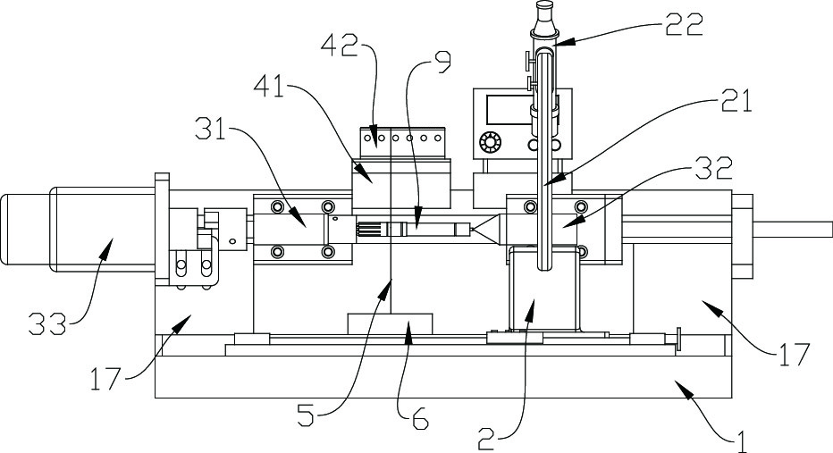
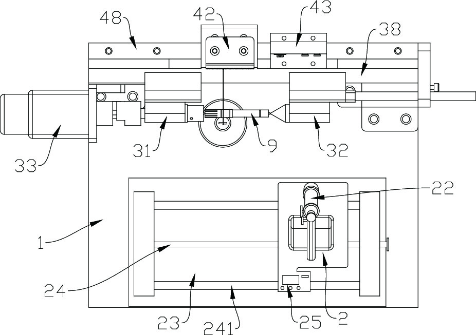
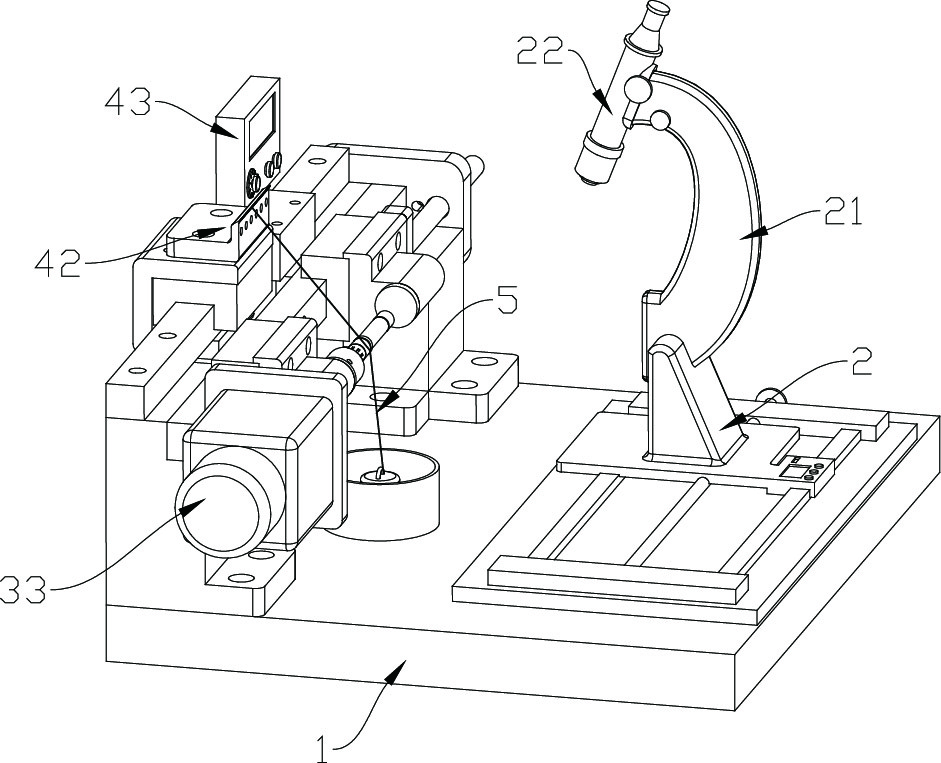
A detection method for representing grinding lines of a columnar part comprises the steps that S10 the columnar part needing to be detected is fixed through a clamping assembly, and a nylon wire withthe smooth surface is arranged on the surface of the columnar part in a lap joint mode; S20 the upper end of the nylon wire is fixed, and the lower end of the nylon wire is connected with a weight, sothat the nylon wire is kept in a falling and tensioning state; S30 a microscope or an magnifying lens is moved, and the visual field area of the microscope or the magnifying lens is aligned with theposition of the nylon wire on the columnar part; S40 the clamping assembly drives the columnar part to rotate for a plurality of circles, then rotation is stopped, the position of the nylon wire on the columnar part in the visual field area of the microscope or the magnifying lens is observed, and the deviation between the position and the position of the nylon wire before rotation is calculated;and S50 whether the detection of the grinding lines of the columnar part is qualified or not is judging according to the deviation. The invention further relates to a detection device, the position ofthe nylon wire on the surface of the part is adopted for calibration, operation is convenient, and no damage is caused to the surface of the part.

Description

technical field [0001] The invention belongs to the technical field of parts detection, and in particular relates to a detection method for characterizing the grinding lines of columnar parts, and also relates to the detection device. Background technique [0002] Columnar parts generally refer to cylindrical parts, such as worms, gear shafts, etc., which are widely used in the industrial field. The columnar parts produced by grinding machine have grinding lines on the surface. The size, slope, depth and other indicators of the grinding lines also affect the use of the parts. Therefore, after the columnar parts are produced in the workshop, they need to be adjusted. The surface grinding texture is characterized, and the characterization results are used as one of the criteria for judging whether the product is qualified. [0003] In the prior art, there is no uniform standard for the detection method of the grinding pattern on the surface of the columnar part. Most of them ...

Claims


Application Information

Patent Timeline
IPC IPC(8): G01N21/956G01B11/00
CPCG01N21/95607G01B11/00G01N2021/95615
Inventor 鱼武涛吴耀庭俞文通周坤朱长钱武甲王文文
Owner NINGBO XIASHA GEARS
Why Eureka
Try Eureka