
Optical fiber interface alignment device

A technology of alignment device and optical fiber interface, which is applied in the direction of light guides, optics, optical components, etc., can solve the problems of unreachable splicing process, low efficiency of optical fiber splicing, high scrap rate, etc., to save time, facilitate splicing operations, and align high efficiency effect

Inactive Publication Date: 2021-02-26
西安万木春信息技术有限公司
View PDF0 Cites 0 Cited by
  • Summary
  • Abstract
  • Description
  • Claims
  • Application Information

AI Technical Summary

Problems solved by technology

[0002] With a large number of optical fibers put into use, it is often necessary to splice the optical fibers. At present, the splicing is mostly done manually. However, due to the technical requirements for the splicing of the optical fiber splicing, the centerlines of the two spliced ​​fibers are often not in a straight line when manually splicing, resulting in failure. The requirements of the splicing process, the efficiency of optical fiber splicing is low, and the scrap rate is high

Method used


Image

  • Optical fiber interface alignment device

Examples


Embodiment Construction

[0014] The present invention will be described in detail below in conjunction with the accompanying drawings and specific embodiments.

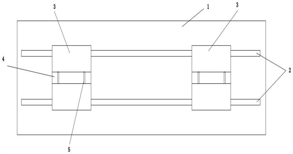
[0015] An optical fiber interface alignment device of the present invention, such as figure 1 As shown, including a base 1, a pair of parallel guide rails 2 are arranged on the base 1, two sliding blocks 3 are arranged on the guide rail 2, and an optical fiber channel 4 is opened on the sliding block 3 along the length direction of the guide rail 2, and the optical fiber on the two sliding blocks 3 The through grooves 4 are arranged opposite and on the same straight line.

[0016] The optical fiber channel 4 is a V-shaped groove.

[0017] The notch of the optical fiber channel 4 is provided with a fixing buckle 5 .

[0018] The fixing buckle 5 is a flexible buckle.

[0019] There are two or more fixing buckles 5 .

[0020] The functions of the main components of an optical fiber interface alignment device of the present invention are as f...


PUM


Abstract

The invention discloses an optical fiber interface alignment device, which comprises a base; wherein a pair of parallel guide rails are arranged on the base, two sliding blocks are arranged on the guide rails, optical fiber through grooves are formed in the sliding blocks in the length direction of the guide rails, and the optical fiber through grooves in the two sliding blocks are oppositely formed and located on the same straight line. According to the optical fiber interface alignment device, two optical fibers needing to be connected are fixed in the optical fiber through grooves of the sliding blocks respectively, alignment can be achieved, the two optical fiber interfaces directly abut against each other through relative movement of the sliding blocks, and subsequent connection operation is facilitated; therefore, the alignment efficiency is high, the continuous process requirement can be met, manual alignment operation is reduced largely, and time is saved.

Description

technical field [0001] The invention belongs to the technical field of electric power auxiliary equipment, and relates to an optical fiber interface alignment device. Background technique [0002] With a large number of optical fibers put into use, it is often necessary to splice the optical fibers. At present, the splicing is mostly done manually. However, due to the technical requirements for the splicing of the optical fiber splicing, the centerlines of the two spliced ​​fibers are often not in a straight line when manually splicing, resulting in failure. According to the requirements of the splicing process, the efficiency of optical fiber splicing is low and the scrap rate is high. Contents of the invention [0003] The purpose of the present invention is to provide an optical fiber interface alignment device, which can realize the rapid alignment of two continuous optical fiber interfaces. [0004] The technical solution adopted in the present invention is that an o...

Claims


Application Information

Patent Timeline
Patent Type & Authority Applications(China)
IPC IPC(8): G02B6/255G02B6/36
CPCG02B6/2555G02B6/3636
Inventor 冯小康余婷婷
Owner 西安万木春信息技术有限公司
Learn More