
A method for estimating the distribution of convective heat transfer coefficients on the primary and secondary sides of a steam generator

A convective heat transfer coefficient and steam generator technology, which is applied in the directions of instrumentation, calculation, design optimization/simulation, etc., can solve the problem of real-time estimation and cannot dynamically output the convective heat transfer coefficient of the primary and secondary sides of the steam generator in real time. Distribution and other issues to achieve the effect of improving safety and economy

Active Publication Date: 2022-03-22
SHANGHAI JIAOTONG UNIV
View PDF7 Cites 0 Cited by
  • Summary
  • Abstract
  • Description
  • Claims
  • Application Information

AI Technical Summary

Problems solved by technology

The main contribution of this patent is to propose a steady-state mathematical model for homogeneous flow of steam generators, but it cannot dynamically output the distribution of convective heat transfer coefficients of the steam generator along the height of the inverted U-shaped tube and the primary and secondary sides in real time.
[0005] In summary, none of the existing public reports involve the real-time estimation of the distribution of convective heat transfer coefficients along the height of the inverted U-shaped tube of the nuclear power steam generator and the primary and secondary sides. This gap needs to be filled.

Method used


Image

  • A method for estimating the distribution of convective heat transfer coefficients on the primary and secondary sides of a steam generator
  • A method for estimating the distribution of convective heat transfer coefficients on the primary and secondary sides of a steam generator
  • A method for estimating the distribution of convective heat transfer coefficients on the primary and secondary sides of a steam generator

Examples


Embodiment Construction

[0106] The present invention will be described in detail below in conjunction with specific embodiments. The following examples will help those skilled in the art to further understand the present invention, but do not limit the present invention in any form. It should be noted that those skilled in the art can make several modifications and improvements without departing from the concept of the present invention. These all belong to the protection scope of the present invention.

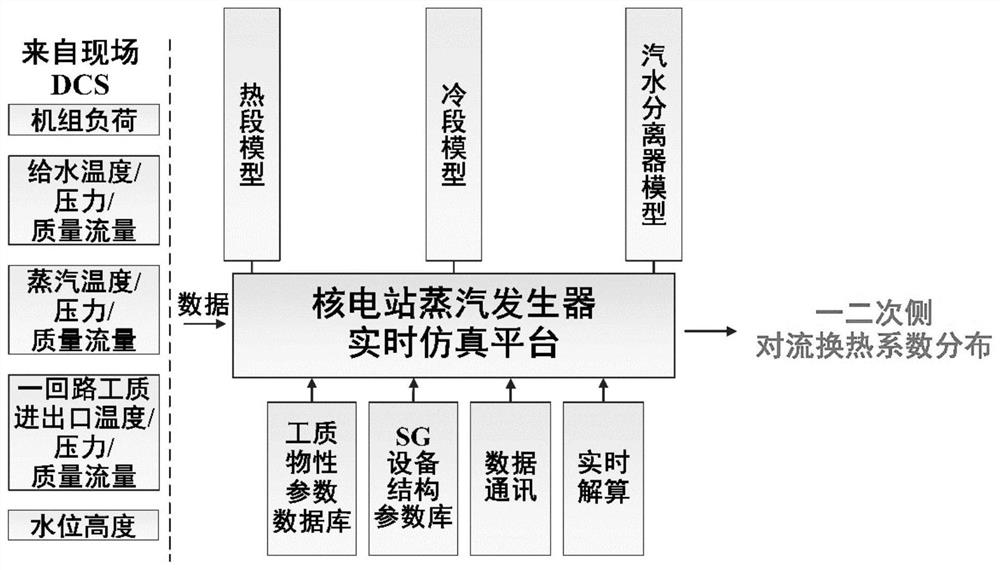
[0107] An embodiment of the present invention provides a method and system for real-time estimation of the convective heat transfer coefficient distribution on the secondary side of a nuclear power steam generator. Taking the steam generator as the research object, according to the specific structure of the steam generator, the steam generator is divided into thermal section, cold section and steam separator. The mechanism model of the steam generator is established based on the dynamic balance of...


PUM


Abstract

The invention provides a method for estimating the distribution of convective heat transfer coefficients on the primary and secondary sides of a steam generator, which specifically includes: obtaining real-time operating data of the steam generator at a given moment; establishing a descending channel model, and obtaining the outlet at the bottom of the descending channel at the current moment The flow rate, temperature and pressure of the liquid-phase working medium; establish a primary circuit coolant model, and obtain the flow velocity, temperature, pressure distribution and primary side convective heat transfer coefficient distribution of the primary circuit coolant along the height of the inverted U-shaped tube at the current moment; establish an ascent Channel model, to obtain the flow velocity, temperature, pressure distribution of the secondary circuit working fluid along the height of the inverted U-shaped tube at the current moment, and the distribution of the secondary side convective heat transfer coefficient; establish a steam-water separator model, and calculate the gas-phase working fluid at the outlet of the steam-water separator, The temperature, pressure and mass flow rate of liquid phase working fluid. The invention can realize the real-time estimation of the distribution of convective heat transfer coefficient on the primary and secondary sides of the steam generator.

Description

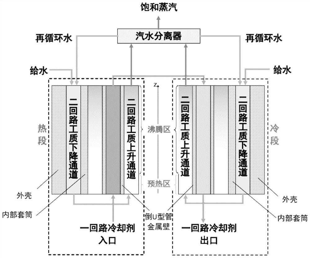
technical field [0001] The invention provides a real-time estimation (identification) method for the distribution of convective heat transfer coefficients of nuclear power steam generators combined with mechanism modeling and DCS (on-site distributed control system of operating units) real-time measurement data, belonging to the technical field of nuclear power plant operation optimization control . Background technique [0002] In a nuclear power plant, the high-temperature and high-pressure coolant from the reactor first enters the inlet of the steam generator, then flows into the inverted U-shaped tube, transfers the heat to the secondary side fluid through the metal tube wall of the inverted U-shaped tube, and then flows out of the U-shaped tube. out of the mouth. On the secondary side, the feed water is mixed with the recirculation fluid separated from the primary and secondary steam-water separators to form mixed water, which flows into the descending channel of the s...

Claims


Application Information

Patent Timeline
Patent Type & Authority Patents(China)
IPC IPC(8): G06F30/20G06F30/28G01D21/02G06F119/08
CPCG06F30/20G06F30/28G01D21/02G06F2119/08
Inventor 惠久武凌君袁景淇胡诗曲邹恒斐栾振华王改霞邓冠华王浩高仕航董贺孙鑫宇
Owner SHANGHAI JIAOTONG UNIV
Learn More