
Joint simulation optimization method and system for microwave microfluid sensor channel values

A microfluidic channel and co-simulation technology, applied in design optimization/simulation, instrumentation, electrical digital data processing, etc., can solve the problem of low sensitivity, achieve reliable performance, simplify the manual design process, and promote the effect of industrialization

Pending Publication Date: 2021-02-26
HANGZHOU DIANZI UNIV
View PDF0 Cites 0 Cited by
  • Summary
  • Abstract
  • Description
  • Claims
  • Application Information

AI Technical Summary

Problems solved by technology

However, among the many sensors used to characterize liquids, their sensitivity is often not high

Method used


Image

  • Joint simulation optimization method and system for microwave microfluid sensor channel values
  • Joint simulation optimization method and system for microwave microfluid sensor channel values
  • Joint simulation optimization method and system for microwave microfluid sensor channel values

Examples


Embodiment 1

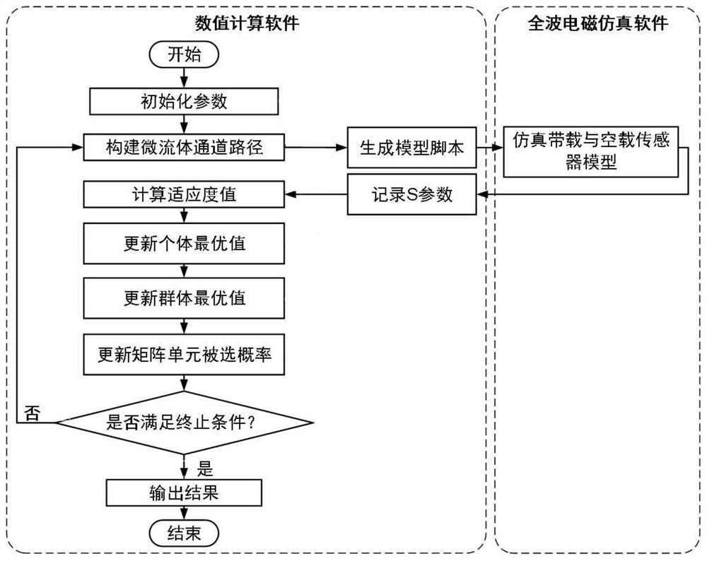
[0049] refer to figure 1 , the present embodiment provides a co-simulation optimization method for channel values ​​of microwave and microfluidic sensors, comprising steps:

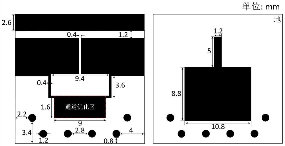
[0050] S1. Initially set the channel optimization area of ​​the microwave and microfluidic sensor and pixelize it into a matrix unit of size MxN;

[0051] S2, initialization program parameter value;

[0052] S3. Construct a plurality of individual microfluidic channels according to the channel search method to form a population;

[0053] S4. Build a model and perform simulation, and calculate the fitness value of the individual microfluidic channel according to the data obtained by the simulation;

[0054] S5. Update the individual optimal channel, the group optimal channel and the probability of each matrix unit being selected in the iterative process according to the fitness value;

[0055] S6. Determine whether the number of iterations reaches the maximum number of iterations; if not, repeat the above...

Embodiment 2

[0080] refer to Figure 10 , the present invention also provides a co-simulation optimization system for microwave and microfluidic sensor channel values, including:

[0081] Initial setting module: Initially set the optimized area of ​​the microwave and microfluidic sensor channel and pixelize it into a matrix unit of size MxN;

[0082] Initialize the module, initialize the program parameter value;

[0083] A channel building block that constructs a plurality of individual microfluidic channels to form a population according to a channel search method;

[0084] The fitness value calculation module constructs a model and performs simulation, and calculates the individual microfluidic channel fitness value according to the data obtained by the simulation;

[0085] The update module updates the individual optimal channel, the group optimal channel and the probability that each matrix unit is selected during the iterative process according to the fitness value;

[0086] Judgin...


PUM


Abstract

The invention discloses a joint simulation optimization method and system for microwave microfluid sensor channel values. The method comprises the following steps: S1, initially setting a microwave microfluid sensor channel optimization area and pixelating the microwave microfluid sensor channel optimization area into matrix units with the size of MxN; s2, initializing a program parameter value; s3, constructing a plurality of individual microfluid channels according to a channel search method to form a population; s4, constructing a model, carrying out simulation, and calculating the fitnessvalue of the individual microfluid channel according to data obtained through simulation; s5, updating the individual optimal channel, the group optimal channel and the probability that each matrix unit is selected in the iteration process according to the fitness value; s6, judging whether the number of iterations reaches the maximum number of iterations or not; and if not, repeating the step S3-S5, and if yes, outputting the optimized microfluid channel value. According to the method, the microwave microfluid sensor channel layout with excellent performance can be obtained quickly, reliablyand automatically.

Description

technical field [0001] The invention relates to the technical field of microwave sensor design, in particular to a co-simulation optimization method and system for channel values ​​of microwave and microfluidic sensors. Background technique [0002] Microwave sensors are playing an increasingly important role in many fields such as medical treatment, biomedicine, and industry due to their high sensitivity, robustness, and low manufacturing and measurement costs. They are also used to characterize the dielectric properties of liquids in microfluidic systems. Therefore, how to accurately and quickly measure the dielectric constant of liquid has become a hot spot of common concern in both academic and industrial circles. [0003] In recent years, the split-ring resonator (Split-ring resonator) and the complementary split-ring resonator (Complementary split-ring resonator) can often show a strong electric field due to their topological structure. When the liquid under test (LUT...

Claims


Application Information

Patent Timeline
Patent Type & Authority Applications(China)
IPC IPC(8): G06F30/20G01R27/26G06F113/08
CPCG06F30/20G01R27/2688G06F2113/08
Inventor 赵文生王彬潇林福康王大伟刘琦王高峰
Owner HANGZHOU DIANZI UNIV
Learn More