
Drivable area detection method and device

A driving area and detection method technology, applied in the field of driving area detection methods and devices, can solve problems such as high equipment cost, inability to drive vehicles, traffic congestion, etc., to improve perception ability, improve detection accuracy and reliability, and reduce impact. Effect

Pending Publication Date: 2021-02-26
苏州挚途科技有限公司
View PDF0 Cites 2 Cited by
  • Summary
  • Abstract
  • Description
  • Claims
  • Application Information

AI Technical Summary

Problems solved by technology

[0003] At present, the drivable area detection technology generally adopts the drivable area detection method based on the binocular camera parallax image, but the drivable area detection method needs to use the binocular camera to capture two left and right images, and obtain the disparity based on the two left and right images. image, so as to detect the feasible area based on the parallax image. Since the parallax image is obtained based on the two images taken on the left and right, the calibration accuracy of the binocular camera is high, which makes the cost of the equipment used for the detection of the drivable area high, and the detection process is difficult. It is cumbersome. The bumps and vibrations during the driving process of the vehicle will affect the detection accuracy, resulting in low detection accuracy of the drivable area and affecting the driving of the vehicle. traffic congestion

Method used


Image

  • Drivable area detection method and device
  • Drivable area detection method and device
  • Drivable area detection method and device

Examples


Embodiment Construction

[0066] In order to make the purpose, technical solutions and advantages of the embodiments of the present invention clearer, the technical solutions in the embodiments of the present invention will be clearly and completely described below in conjunction with the drawings in the embodiments of the present invention. Obviously, the described embodiments are only It is a part of embodiments of the present invention, but not all embodiments. The components of the embodiments of the invention generally described and illustrated in the figures herein may be arranged and designed in a variety of different configurations. Accordingly, the following detailed description of the embodiments of the invention provided in the accompanying drawings is not intended to limit the scope of the claimed invention, but merely represents selected embodiments of the invention. Based on the embodiments of the present invention, all other embodiments obtained by those skilled in the art without making...


PUM


Abstract

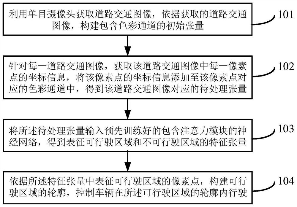
The invention provides a drivable area detection method and device, and the method comprises the steps: obtaining a road traffic image through a monocular camera, and constructing an initial tensor comprising a color channel according to the obtained road traffic image; for each road traffic image, obtaining coordinate information of each pixel point in the road traffic image, and adding the coordinate information of the pixel point to the color channel corresponding to the pixel point to obtain a to-be-processed tensor corresponding to the road traffic image; inputting the tensor to be processed into a pre-trained neural network containing an attention module to obtain feature tensors representing a drivable area and a non-drivable area; and constructing a contour of the drivable area according to the pixel points representing the drivable area in the feature tensor, and controlling the vehicle to drive in the contour of the drivable area. The detection precision of a drivable area can be improved.

Description

technical field [0001] The invention relates to the technical field of road traffic, in particular to a method and device for detecting a drivable area. Background technique [0002] The drivable area detection technology is a key technology in the assisted driving system and the automatic driving system. Technical Support. Among them, the non-driving area mainly includes static obstacles on the road, such as the area where cones and guardrails are located, and dynamic obstacles, such as areas where vehicles and pedestrians are located, curbs on both sides of the road, and roads in the middle of the road. construction area, etc. [0003] At present, the drivable area detection technology generally adopts the drivable area detection method based on the binocular camera parallax image, but the drivable area detection method needs to use the binocular camera to capture two left and right images, and obtain the disparity based on the two left and right images. image, so as to...

Claims


Application Information

Patent Timeline
IPC IPC(8): G06K9/00G06K9/62G06K9/72G06N3/04G06N3/08
CPCG06N3/08G06V20/58G06V30/274G06N3/045G06F18/253G06F18/214
Inventor 倪光一钱少华韩志华张旭杜一光
Owner 苏州挚途科技有限公司
Learn More