Building deflection determination method and device and electronic equipment

A determination method and construction technology, applied in the direction of measuring devices, optical devices, image data processing, etc., can solve problems such as low work efficiency, low precision, and relatively harsh measurement environment requirements, and achieve the goal of improving accuracy and speed of determination Effect

Pending Publication Date: 2021-02-26
杭州鲁尔物联科技有限公司
View PDF0 Cites 1 Cited by
  • Summary
  • Abstract
  • Description
  • Claims
  • Application Information

AI Technical Summary

Problems solved by technology

[0003] Exemplary, the current methods for measuring the deflection of bridges mainly include the following: the level method, using the measuring tool leveling rod and level to measure the vertical height difference between two points on the bridge surface to calculate the deflection value, and the measurement environment requirements are relatively harsh , and the range of measuring deflection is relatively small, and the measuring points should not be too many; the dial indicator and dial indicator measurement method uses the gear rotation device to amplify the displacement data transmitted by the measuring rod, and the detected data is in the circular The display on the dial can only be used under the bridge or in the occasion where the support can be erected on the bridge pier. The support must be erected, which leads to low work efficiency, not very convenient to use, and great limitations in field application; connecting pipe measurement The method uses the principle of "communicator", that is, the pressure at the same level is the same. The connecting pipe method generally uses a soft plastic pipe with a diameter of about 10mm and some three-way connectors. The connecting pipe is placed on the bridge. The millimeter scale is read manually, but the accuracy is low; the laser interferometer method, the prism or reflector is installed on the point to be measured, and then the laser interferometer is used to measure the distance change of the observation point, but the vibration amplitude of the bridge After exceeding a certain range, the light spot will not be captured, and the corresponding measurement effect will not be achieved; digital image processing technology measurement method, post or fix a special-shaped target on the bridge, and calculate the position of the target in the two images before and after the bridge displacement displacement, and then calculate the actual displacement of the bridge through spatial coordinate conversion, but it is necessary to install a target on the side of the bridge or the box girder of the bridge. The construction needs to be licensed by the government and has certain technical difficulties. It cannot be operated portable Require

Method used


Image

  • Building deflection determination method and device and electronic equipment
  • Building deflection determination method and device and electronic equipment
  • Building deflection determination method and device and electronic equipment

Examples


Embodiment 1

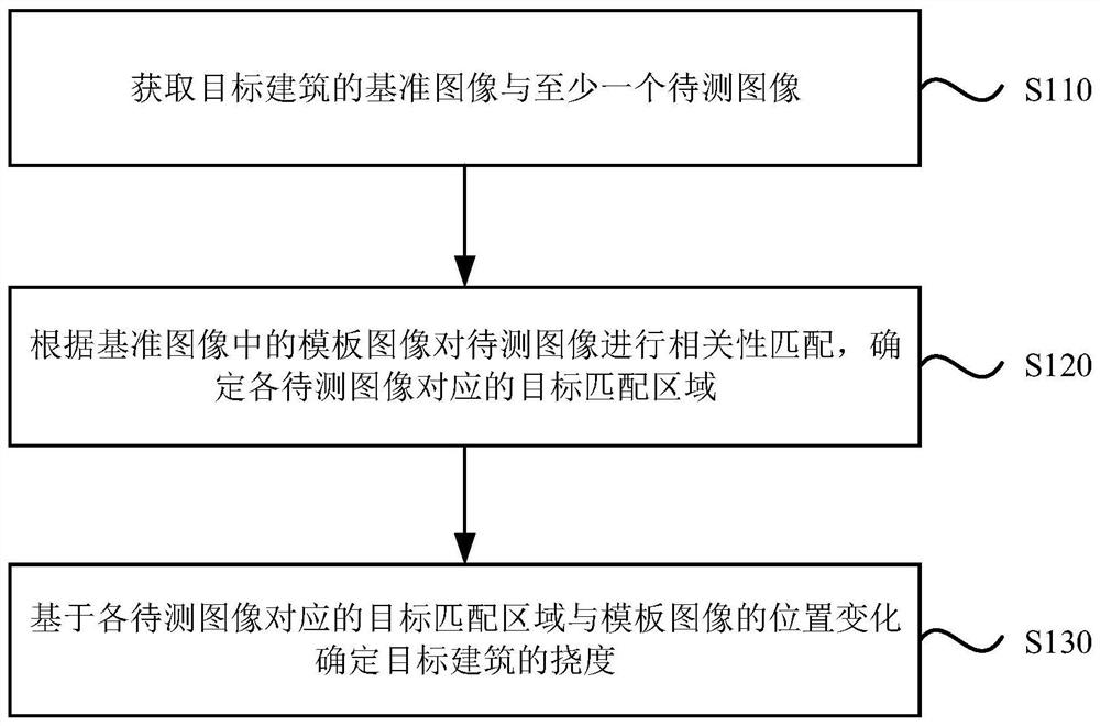
[0031] figure 1 It is a schematic flowchart of a method for determining the deflection of a building provided by Embodiment 1 of the present invention. This embodiment is applicable to the situation where the deflection of the target building needs to be determined according to the captured images of the target building at various time points. The method can be determined by the deflection of the building Determine the device to perform, the device can be implemented by hardware and / or software, the method specifically includes the following steps:

[0032] S110. Acquire a reference image of a target building and at least one image to be tested.

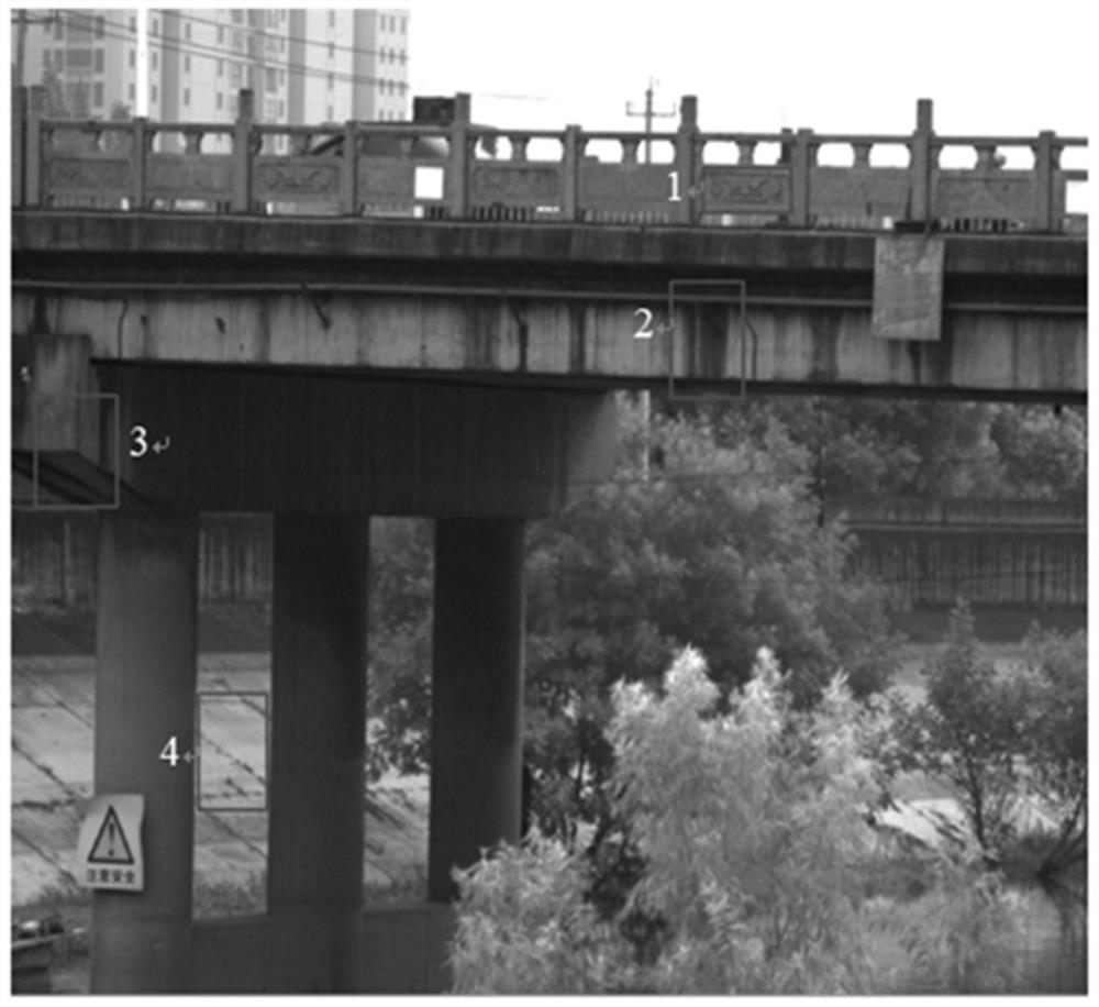
[0033] Wherein, the target building refers to a building whose deflection needs to be determined so as to judge its structural deformation degree, such as a bridge, a railway, a wall or a main beam of a house, etc. In this embodiment, the target building may be a bridge as an example. The reference image and at least one image to be...

Embodiment 2

[0069] Figure 4 It is a schematic flow chart of a method for determining the deflection of a building provided by Embodiment 2 of the present invention. On the basis of the above-mentioned embodiments, this embodiment "based on the target matching area corresponding to each of the images to be tested and the template image position changes to determine the deflection of the target building" was further optimized. The explanations of terms that are the same as or corresponding to the above-mentioned embodiments will not be repeated here. see Figure 4 , the building deflection determination method provided in this embodiment includes:

[0070] S410. Acquire a reference image of the target building and at least one image to be tested.

[0071] S420. Perform correlation matching on the images to be tested according to the template image in the reference image, and determine the target matching area corresponding to each image to be tested.

[0072] S430. Determine the positi...

Embodiment 3

[0091] Figure 7 It is a structural schematic diagram of a building deflection determination device provided by Embodiment 3 of the present invention. This embodiment is applicable to the situation where it is necessary to determine the deflection of the target building according to the captured images of the target building at various time points. The device specifically includes: An acquisition module 710 , a matching module 720 and a deflection determination module 730 .

[0092] An image acquisition module 710, configured to acquire a reference image of the target building and at least one image to be tested;

[0093] The matching module 720 is used to perform correlation matching on the image to be tested according to the template image in the reference image, and determine the target matching area corresponding to each image to be tested;

[0094] The deflection determination module 730 is configured to determine the deflection of the target building based on the positi...


PUM


Abstract

The invention discloses a building deflection determination method and device and electronic equipment. The method comprises the following steps: acquiring a reference image and at least one to-be-measured image of a target building; and performing correlation matching on the to-be-detected images according to the template images in the reference image, determining target matching areas corresponding to the to-be-detected images, and determining the deflection of the target building based on the position change of the target matching areas corresponding to the to-be-detected images and the template images so as to determine the deflection of the target building based on image matching. According to the embodiment of the invention, the invention improves the accuracy of the determined building deflection while improving the determination speed of the building deflection, is suitable for the measurement of the deflection of a building with lower contrast, and is also suitable for the determination of the deflection in a scene with a harsh measurement environment.

Description

technical field [0001] Embodiments of the present invention relate to the technical field of building deformation testing, in particular to a method, device and electronic equipment for determining building deflection. Background technique [0002] Buildings such as bridges, house beams, and high-rise buildings are related to the safety of people's lives and property. Deflection refers to the bending value of a building or its components in the horizontal or vertical direction. For example, the middle part of a bridge will bend downward, and high-rise buildings will bend sideways. As an important key indicator of building safety evaluation, deflection is an important part of building inspection, which can directly reflect whether the deformation of building structure exceeds its safe allowable range, and can provide effective parameters for damage identification and health monitoring of building structures. [0003] Exemplary, the current methods for measuring the deflecti...

Claims


Application Information

Patent Timeline
IPC IPC(8): G06T7/00G06T7/13G06T7/73G06K9/62G01B11/16
CPCG06T7/0004G06T7/13G06T7/73G01B11/16G06T2207/10004G06T2207/20016G06T2207/30132G06V10/751
Inventor 王一妍赵文一江子君
Owner 杭州鲁尔物联科技有限公司
Why Eureka
Try Eureka