
An electronic component magnetic ring has automatic wrapping wire processing and production equipment

A technology for electronic components and production equipment, which is applied in the field of automatic wrapping wire processing and production equipment for electronic component magnetic rings, which can solve the problems of cumbersome steps to adjust the magnetic ring position and inconvenient wrapping wires, and achieve the effect of increased winding and reduced friction

Active Publication Date: 2022-05-13
DONGGUAN UNIV OF TECH
View PDF8 Cites 0 Cited by
  • Summary
  • Abstract
  • Description
  • Claims
  • Application Information

AI Technical Summary

Problems solved by technology

[0004] Aiming at the deficiencies of the prior art, the present invention provides an electronic component magnetic ring with automatic wire-covering processing and production equipment, which solves the problem that most of the magnetic rings proposed in the above-mentioned background technology have different sizes and models, so most of them are still produced by people. Wrap the magnetic ring. In the small magnetic ring wrapping, usually use a clamp to hold half of the magnetic ring, and then wrap the magnetic ring manually. After wrapping half of the magnetic ring Then loosen the clamp and turn it over and continue wrapping the magnetic ring, so as not to cause inconvenience in the wrapping process due to the small volume of the magnetic ring during the wrapping process, and repeatedly adjust the position of the magnetic ring It also causes problems such as cumbersome steps

Method used


Image

  • An electronic component magnetic ring has automatic wrapping wire processing and production equipment
  • An electronic component magnetic ring has automatic wrapping wire processing and production equipment
  • An electronic component magnetic ring has automatic wrapping wire processing and production equipment

Examples


Embodiment Construction

[0028] The following will clearly and completely describe the technical solutions in the embodiments of the present invention with reference to the accompanying drawings in the embodiments of the present invention. Obviously, the described embodiments are only some, not all, embodiments of the present invention.

[0029] In the description of the present invention, unless otherwise stated, the meaning of "plurality" is two or more; the terms "upper", "lower", "left", "right", "inner", "outer" , "front end", "rear end", "head", "tail", etc. indicate the orientation or positional relationship based on the orientation or positional relationship shown in the drawings, and are only for the convenience of describing the present invention and simplifying the description, rather than indicates or implies that the device or element referred to must have a particular orientation, be constructed and operate in a particular orientation, and therefore should not be construed as limiting the...


PUM


Abstract

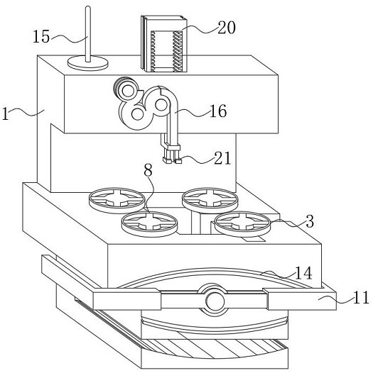
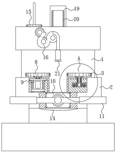
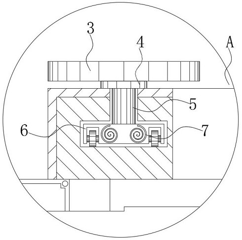
The invention discloses an electronic component magnetic ring with automatic wire-wrapped processing and production equipment, including a wire-wrapped case, an operation table is arranged at the bottom of the wire-wrapped case, a control motor is installed inside the operation table, and the covered wire A straightening assembly is installed under the upper front wire seat of the chassis, racks are provided on both sides of the inner cavity of the insertion rod, and the bottom of the insertion rod is connected with a plug-in head, and one side of the plug-in head is internally provided with a The hydraulic device, and the left end of the hydraulic device is equipped with a cutter. The present invention arranges the swivel frame and the plug-in head on the front and the top of the operation table, and through the setting of the swivel frame and the plug-in head, it is convenient to connect the plug-in head and the swivel frame. Inter-work operation, the rotating frame drives the wrapped wire to rotate to wrap the magnetic ring, and at the same time, through the setting of the wire removal head, it is convenient to press the protruding covered wire through the magnetic ring, avoiding the staff to manually wind the magnetic ring to increase the working time. Thereby, it is beneficial to form the automatic winding of the magnetic ring.

Description

technical field [0001] The invention relates to the technical field of magnetic ring electronic components, in particular to an electronic component magnetic ring with automatic wire-wrapped processing and production equipment. Background technique [0002] The magnetic ring is a ring-shaped magnetizer. The magnetic ring is an anti-interference component commonly used in electronic circuits. It has a good suppression effect on high-frequency noise. It is generally made of ferrite materials. The magnetic ring has different frequencies at different frequencies. Different impedance characteristics, generally the impedance is very small at low frequencies, when the signal frequency increases, the impedance of the magnetic ring increases sharply, the higher the signal frequency, the easier it is to radiate out, and the general signal line has no shielding layer. These signal lines become very good antennas, receiving all kinds of messy high-frequency signals in the surrounding en...

Claims


Application Information

Patent Timeline
Patent Type & Authority Patents(China)
IPC IPC(8): H01F41/08
CPCH01F41/08
Inventor 洪颖陈奕傧潘章景
Owner DONGGUAN UNIV OF TECH
Learn More