Holder for thermally contacting an electronic component and a cooling body

A technology for holding devices and electronic components, applied in circuit thermal devices, printed circuit components, electrical equipment structural components, etc., can solve problems such as inability to install thermal pads, forgetting to install thermal pads, and inability to compensate for offsets or angles.

Pending Publication Date: 2021-02-26
EBM PAPST MULFINGEN GMBH & CO KG
View PDF0 Cites 0 Cited by
  • Summary
  • Abstract
  • Description
  • Claims
  • Application Information

AI Technical Summary

Problems solved by technology

[0006] The problem is that since the two installation steps are performed separately, it is possible to forget to install the thermal pad
And since the mounting area of ​​the thermal pad is usually then covered by the printed circuit board, such errors can easily go unnoticed
Although errors can be detected by visual monitoring, this is complex and expensive
[0007] That aside, besides missing the thermal pad entirely, there is no control over whether the part is flush against the thermal pad, or if there is an air bubble between the thermal pad and the part due to a mounting defect or misalignment of the thermal pad or displacement such that the intended surface of the part is not completely against the thermal pad
Since dislocations or displacements are also likely to occur during the mounting of the component to the thermal pad, such flaws cannot or are difficult to detect with visual inspection
[0008] Furthermore, thermal pads are us...

Method used


Image

  • Holder for thermally contacting an electronic component and a cooling body
  • Holder for thermally contacting an electronic component and a cooling body
  • Holder for thermally contacting an electronic component and a cooling body

Examples


Embodiment Construction

[0052] The accompanying drawings are illustrative schematic diagrams. The same reference numbers in the figures refer to the same functional and / or structural features.

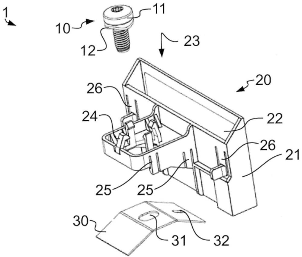
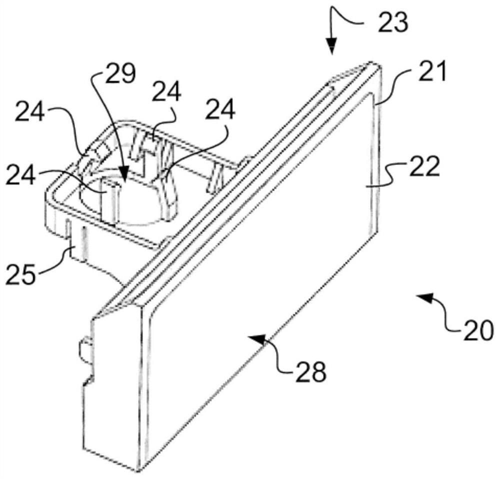
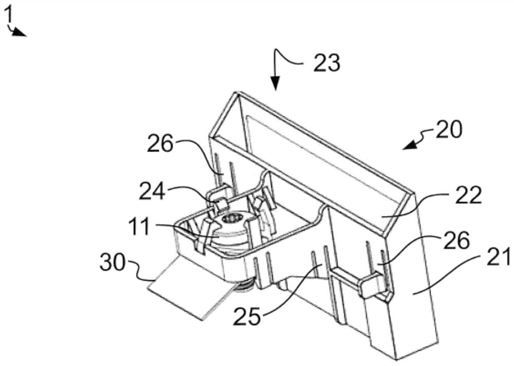
[0053] figure 1 The holding device 1 is shown with three components, wherein the three components, namely the holding body 20 , the tensioning element 10 and the spring element 30 , are separated from one another. In addition, the holding body 20 is separately shown in a rotated state in figure 2 middle. The holding device 1 is shown in the state diagram in which its components are connected together in an anti-lost manner image 3 and Figure 4 middle. Figure 5 and Figure 6 shown in section Figure 1 to Figure 4 The different installed states of the holding device 1 are shown, so that the following description basically applies to all of the figures.

[0054] The retaining body 20 forms four first snap-in elements 24 on its engaging portion 21, these first snap-in elements are used for ringing the...


PUM


Abstract

The invention provides a holder for thermally contacting an electronic component mounted on a printed circuit board and a cooling body. The holder has a holding body, a spring member, and a tensioningmember. The holding body forms a cavity that corresponds to the electronic component to receive the electronic component. The holder also has a connecting section and a thermally conductive heat conductive section adjacent to the cavity and having a heat conduction function. The heat conduction section is provided with a heat joint surface deviating from the cavity. The tensioning member is configured to tension the spring member. The spring member is designed to be supported on a counter-holding element in a tensioned state and to exert a force on the holding body and/or the component that can be accommodated in the cavity of the holding body, and to move the holding body with the engagement surface towards the cooling body and/or press against the cooling body.

Description

technical field [0001] The invention relates to a holding device for thermally contacting an electronic component mounted on a printed circuit board with a heat sink. Background technique [0002] Electronic components, in particular line electronic components (Leitungselektronik-Bauteil), which are mounted on printed circuit boards and which generate and release heat during operation, generally require cooling. For this reason, it is often necessary to connect such components to a cooling body. [0003] If the radiator is large and heavy or integrally formed with the housing containing the printed circuit board and electronic components, the electronic components are often placed in the housing when the printed circuit board is installed in the housing containing the printed circuit board. Thermally connected to heat sink. [0004] The prior art generally requires the use of several separate components to connect electronic components. Such systems include, for example, ...

Claims


Application Information

Patent Timeline
IPC IPC(8): H01L23/40H05K7/20
CPCH01L23/4006H05K7/2049H05K7/205H01L2023/405H01L2023/4087H05K7/20409H05K7/209H01L23/40H01L23/36H05K1/0209H05K7/20445
Inventor 克里斯托夫·霍德尔巴赫亚历山大·吕斯特尼科·伊尔施莱茵
Owner EBM PAPST MULFINGEN GMBH & CO KG
Why Eureka
Try Eureka