Power transmission line double-wire tackle

A transmission line, double-conductor technology, applied in the direction of overhead lines/cable equipment, etc., can solve the problems of low work efficiency, many insecurity factors, and large distances, and achieve the effect of flexible and convenient operation, improved work efficiency, and labor-saving movement.

Pending Publication Date: 2021-02-26
TIELING POWER SUPPLY COMPANY OF STATE GRID LIAONING ELECTRIC POWER COMPANY +1
View PDF0 Cites 2 Cited by
  • Summary
  • Abstract
  • Description
  • Claims
  • Application Information

AI Technical Summary

Problems solved by technology

[0003] When the single phase of the line is repaired with two conductors, the pulley is usually placed on the lower conductor of the phase or the corresponding conductor for repair. After the pulley exits the conductor and the insulator at a certain distance, due to gravity, the distance between the conductor where the tackle is located and the other conductor of the phase is enlarged. Carry out inspection and maintenance; especially when installing spacers on the line, since the two ends of the spacer need to be installed on two different wires, the problem is more obvious, and ground personnel need to use ropes to pull the wires closer and then repair them There are many unsafe factors in the method, more personnel are required, the multi-working area has high terrain requirements, and the work efficiency is low. Therefore, the present invention proposes a double-conductor tackle for power transmission lines to solve the problems existing in the prior art

Method used


Image

  • Power transmission line double-wire tackle
  • Power transmission line double-wire tackle
  • Power transmission line double-wire tackle

Examples


Embodiment Construction

[0015] In order to deepen the understanding of the present invention, the present invention will be further described below in conjunction with the examples, which are only used to explain the present invention, and do not constitute a limitation to the protection scope of the present invention.

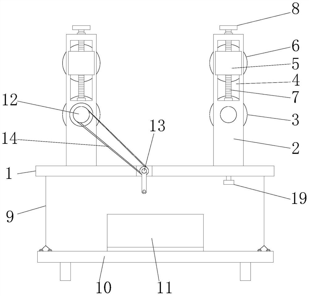
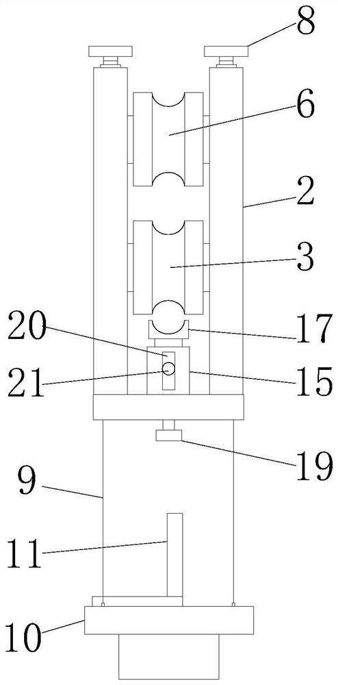
[0016] according to figure 1 , 2 As shown in . 2 and the first wire wheel 3, the support plate 2 is provided with two groups before and after, and the first wire wheel 3 is installed on the bottom between the support plates 2 of the two groups before and after, and the inside of the two groups of support plates 2 Above are provided with chute 4, and sliding block 5 is installed in the chute 4, the second wire pulley 6 is rotatably installed between the two groups of sliders 5, and threaded screw rod 7 is rotatably installed in the chute 4 , and threaded screw rod 7 runs through the slider 5 and is threadedly adapted, the upper end of the threaded screw rod 7 extends out of the supp...


PUM


Abstract

The power transmission line double-wire pulley comprises a mounting plate and wire wheel assemblies, wherein the wire wheel assemblies are arranged on the left side and the right side of the top of the mounting plate correspondingly, each wire wheel assembly comprises supporting plates and a first wire wheel, the supporting plates are divided into a front set and a rear set, and the first wire wheels are rotatably mounted below the position between the front set of supporting plates and the rear set of supporting plates; sliding grooves are formed in the upper portions of the inner sides of the two sets of supporting plates correspondingly, sliding blocks are movably installed in the sliding grooves, a second wire wheel is rotatably installed between the two sets of sliding blocks, threaded lead screws are rotatably installed in the sliding grooves, and the threaded lead screws penetrate through the sliding blocks and are in threaded fit with the sliding blocks. A second wire wheel anda first wire wheel are designed, the second wire wheel is installed on an upper wire, the first wire wheel is installed on a lower wire, the problem that the distance between two wires is large during double-wire line span inner repairing can be effectively solved, the first wire wheel can be driven to rotate by rotating a crank, an operator can move in a more labor-saving mode, operation is moreflexible and convenient, and the repairing efficiency is improved; and working efficiency is improved.

Description

technical field [0001] The invention relates to the technical field of electric wire maintenance equipment, in particular to a double-conductor pulley for power transmission lines. Background technique [0002] At this stage, the repair of transmission line conductors and lightning conductors is usually carried out by the method of pulling out wires; [0003] When the single phase of the line is repaired with two conductors, the pulley is usually placed on the lower conductor of the phase or the corresponding conductor for repair. After the pulley exits the conductor and the insulator at a certain distance, due to gravity, the distance between the conductor where the tackle is located and the other conductor of the phase is enlarged. Carry out inspection and maintenance; especially when installing spacers on the line, since the two ends of the spacer need to be installed on two different wires, the problem is more obvious, and ground personnel need to use ropes to pull the w...

Claims


Application Information

Patent Timeline
Patent Type & Authority Applications(China)
IPC IPC(8): H02G1/02
CPCH02G1/02
Inventor 孙权索巍武高源王书博邢国峰王通丁浩伦张永谦相鹏程张滨显吕志莹冯雷赵金张天堃傅殿浩钱勇张建国
Owner TIELING POWER SUPPLY COMPANY OF STATE GRID LIAONING ELECTRIC POWER COMPANY
Why Eureka
Try Eureka