Motor, air supply device and household appliance

A technology of air supply device and rotor structure, which is applied in electromechanical devices, pump devices, components of pumping devices for elastic fluids, etc., which can solve the inflexibility of the mutual position of the stator and the rotor, which is not conducive to the lightweight design of products, and increases the number of products Size and other issues, to achieve the effect of reducing weight, improving overall stability, and reducing counterweight settings

Active Publication Date: 2021-02-26
GD MIDEA ENVIRONMENT APPLIANCES MFG +1
View PDF9 Cites 0 Cited by
  • Summary
  • Abstract
  • Description
  • Claims
  • Application Information

AI Technical Summary

Problems solved by technology

[0002] In the prior art, conventional motors are composed of a stator and a rotor that are nested inside and outside each other. When the motor is driven externally, the load is usually driven by the motor's shaft to rotate, so due to the limitation of the motor's own structure, it will increase the overall load. The size of the product in the axial direction, in which the stator and the rotor are coaxially arranged, and a closed structure needs to be formed in the circumferential direction, so there is a problem that the mutual position of the stator and the rotor is not flexible and occupies a large space, which is not conducive to the light weight of the product quantitative design

Method used


Image

  • Motor, air supply device and household appliance
  • Motor, air supply device and household appliance
  • Motor, air supply device and household appliance

Examples


Embodiment 1

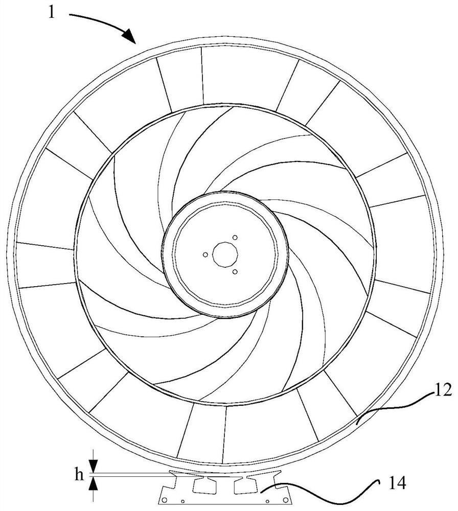
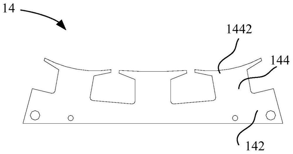
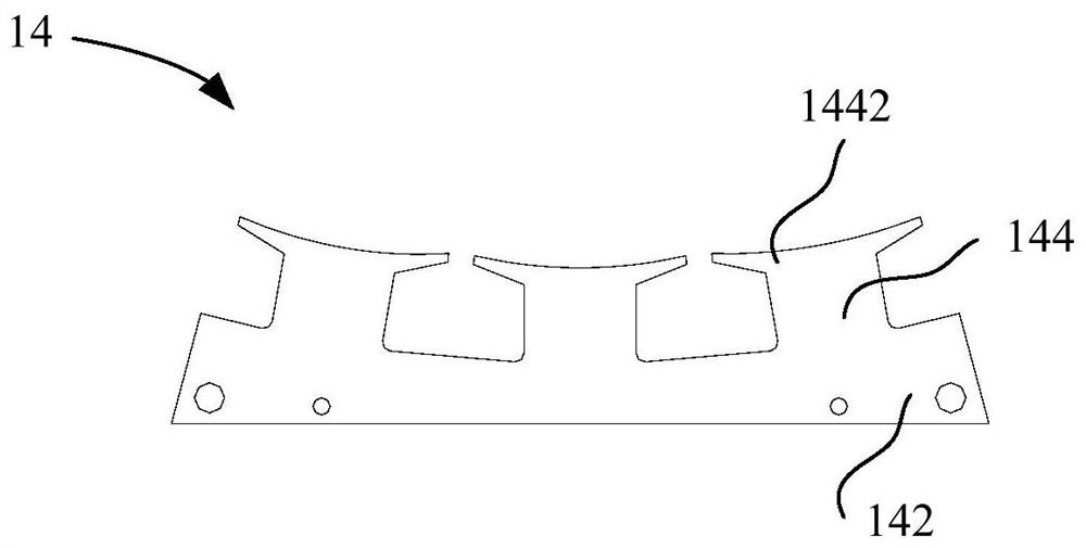
[0120] Such as Figure 1 to Figure 4As shown, one embodiment of the present application proposes a motor 1 , including a rotor structure 12 and a stator structure 14 that are detachably connected. Wherein, the rotor structure 12 is circular, the stator structure 14 is arranged on one side of the rotor structure 12 along the radial direction and there is a gap between the rotor structure 12, the stator structure 14 includes at least one stator arranged along the circumference of the rotor structure 12 The iron core 142 is used to form a driving force on the rotor structure 12 through the stator iron core 142 , and then drive the rotor structure 12 to rotate. The motor 1 is provided with a drive area, the drive area includes a stator core 142 and the part where the rotor structure 12 and the stator structure 14 are facing each other, so that the stator structure 14 in the drive area interacts with the rotor structure 12 to generate a drive rotor structure 12 The driving force o...

Embodiment 2

[0127] Another embodiment of the present application provides a motor 1, including a detachably connected rotor structure 12 and a stator structure 14, wherein the rotor structure 12 is in the shape of a ring, and the stator structure 14 is arranged on one side of the rotor structure 12 along the radial direction. The stator structure 14 includes at least one stator core 142 arranged along the circumference of the rotor structure 12 to form a driving force for the rotor structure 12 through the stator core 142, thereby driving the rotor structure 12 to rotate . Such as figure 1 As shown, the stator structure 14 includes a stator core 142 provided with three stator teeth 144, and windings are arranged on the stator teeth 144, and the polarities of the two adjacent stator windings are different, and the two adjacent stator windings Simultaneously energize, so that the stator structure 14 generates a magnetic field to drive the rotor structure 12 to rotate, specifically, first e...

Embodiment 3

[0135] Another embodiment of the present application provides a motor 1 , including a rotor structure 12 and a stator structure 14 , and the rotor structure 12 is detachably connected to the rotor structure 12 . Wherein, the rotor structure 12 is circular, the stator structure 14 is arranged on one side of the rotor structure 12 and there is a gap between the rotor structure 12, the stator structure 14 includes at least one stator core 142 arranged along the circumference of the rotor structure 12, A driving force is formed on the rotor structure 12 through the stator core 142 to drive the rotor structure 12 to rotate.

[0136] Such as Figure 4 As shown, the rotor structure 12 includes a plurality of magnetic pieces 122 , and the stator structure 14 is arranged corresponding to the magnetic pieces 122 . Wherein, a plurality of magnetic pieces 122 are arranged continuously along the circumferential direction.

[0137] Further, the magnetic member 122 is a magnetic sheet, and...


PUM


Abstract

The invention provides a motor, an air supply device and a household appliance, and the motor comprises a rotor structure; a stator structure which is detachably connected with the rotor structure, wherein the stator structure comprises at least one stator iron core arranged on one side of the rotor structure in the radial direction and is used for driving the rotor structure to rotate. Accordingto the technical scheme, eccentric arrangement between the motor and the load can be achieved, the overall space occupation of the motor can be reduced, the arrangement positions of the rotor structure and the stator structure can be changed according to the specific structure of the load, light weight can be achieved, and the application range is wide.

Description

technical field [0001] The present invention relates to the technical field of fans, in particular to a motor, an air supply device and a household appliance. Background technique [0002] In the prior art, conventional motors are composed of a stator and a rotor that are nested inside and outside each other. When the motor is driven externally, the load is usually driven by the motor's shaft to rotate, so due to the limitation of the motor's own structure, it will increase the overall load. The size of the product in the axial direction, in which the stator and the rotor are coaxially arranged, and a closed structure needs to be formed in the circumferential direction, so there is a problem that the mutual position of the stator and the rotor is not flexible and occupies a large space, which is not conducive to the light weight of the product Quantitative design. Contents of the invention [0003] The present invention aims to solve at least one of the technical problems...

Claims


Application Information

Patent Timeline
Patent Type & Authority Applications(China)
IPC IPC(8): H02K7/14H02K1/16F04D25/08F04D29/70F04D29/32
CPCH02K7/14H02K1/165F04D25/08F04D29/703F04D29/325F04D29/70H02K1/16F04D29/32H02K1/14
Inventor 邱水兵罗伟锦梁显堂陈炜杰叶似锦
Owner GD MIDEA ENVIRONMENT APPLIANCES MFG
Why Eureka
Try Eureka