
Cooling device of power converter and power converter

A technology for power converters and cooling devices, which is applied in the direction of output power conversion devices, cooling/ventilation/heating transformation, electrical components, etc., and can solve the problems of water pipe side wall impact, coolant flow dead zone, poor cooling effect, etc. , to achieve uniform flow velocity, improve heat dissipation efficiency, and reduce flow velocity

Pending Publication Date: 2021-02-26
SHANGHAI VALEO AUTOMOTIVE ELECTRICAL SYST
View PDF0 Cites 2 Cited by
  • Summary
  • Abstract
  • Description
  • Claims
  • Application Information

AI Technical Summary

Problems solved by technology

[0002] Existing power converters use water-cooling to cool internal components. The power converter includes a straight-through water pipe. The water pipe and the housing are assembled together. The heat generated by the internal components is cooled by the cooling liquid in the water pipe. There will be poor circulation in the water pipe. If the coolant flow rate is too high, it will easily cause impact on the side wall of the water pipe. At the same time, there will be a dead zone of coolant flow, and the cooling effect will be poor.

Method used


Image

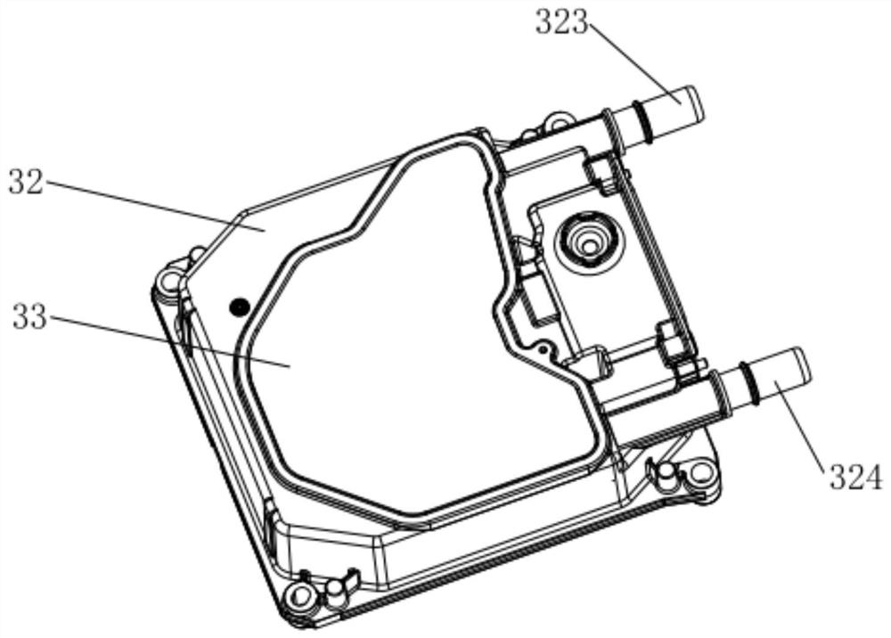
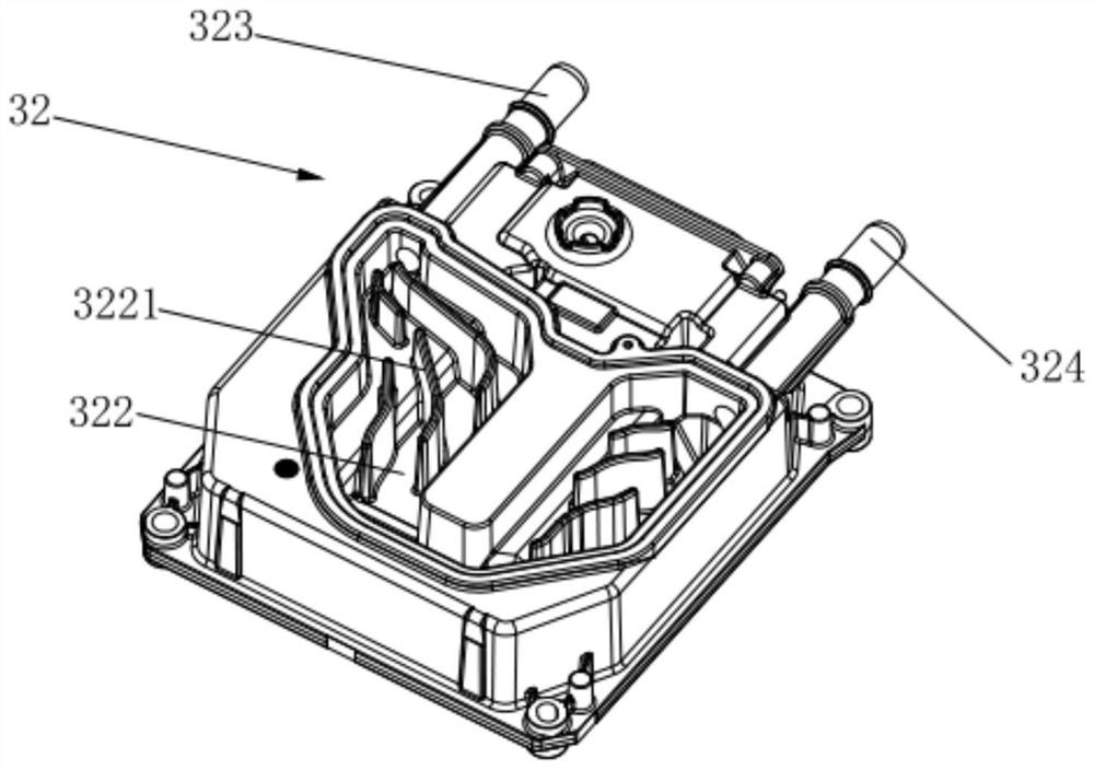
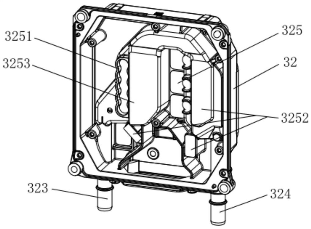
  • Cooling device of power converter and power converter
  • Cooling device of power converter and power converter
  • Cooling device of power converter and power converter

Examples


Embodiment Construction

[0036] In order to make the technical problems solved by the present invention, the technical solutions adopted and the technical effects achieved clearer, the technical solutions of the embodiments of the present invention will be further described in detail below in conjunction with the accompanying drawings. Obviously, the described embodiments are only the technical solutions of the present invention. Some, but not all, embodiments. Based on the embodiments of the present invention, all other embodiments obtained by those skilled in the art without making creative efforts belong to the protection scope of the present invention.

[0037] In the description of the present invention, unless otherwise clearly specified and limited, the terms "connected", "connected" and "fixed" should be understood in a broad sense, for example, it can be a fixed connection, a detachable connection, or an integrated ; It can be a mechanical connection or an electrical connection; it can be a d...


PUM


Abstract

The invention discloses a cooling device of a power converter and the power converter, and belongs to the technical field of power converters. The cooling device of the power converter comprises a shell and a lower cover plate, a communication groove and a mounting cavity are formed in the shell, openings of the communication groove and the mounting cavity face opposite directions, and a flow guide rib is arranged on the communication groove to separate the communication groove; the lower cover plate is arranged on the shell, the lower cover plate and the communication groove form a waterway channel, and a diversion rib divides the waterway channel into shunting channels. The power converter comprises the cooling device of the power converter. According to the cooling device of the power converter and the power converter, the diversion rib is arranged in the communication groove to reduce a cooling liquid flowing dead zone, and a heat dissipation part is arranged in the mounting cavity, so that heat conduction between the to-be-cooled element and the waterway channel is improved, and the cooling efficiency is improved.

Description

technical field [0001] The invention relates to the technical field of power converters, in particular to a cooling device for a power converter and a power converter. Background technique [0002] Existing power converters use water-cooling to cool internal components. The power converter includes a straight-through water pipe. The water pipe and the housing are assembled together. The heat generated by the internal components is cooled by the cooling liquid in the water pipe. There will be poor circulation in the water pipe. If the coolant flow rate is too high, it will easily cause impact on the side wall of the water pipe. At the same time, there will be a dead zone in the coolant flow, and the cooling effect will be poor. Contents of the invention [0003] An object of the present invention is to provide a cooling device for a power converter to improve cooling efficiency. [0004] For reaching this purpose, the present invention adopts following technical scheme: ...

Claims


Application Information

Patent Timeline
Patent Type & Authority Applications(China)
IPC IPC(8): H05K7/20H05K5/02H02M1/00
CPCH05K7/20927H05K7/20272H05K5/0217H02M1/00
Inventor 梁翠平白玉峰董天源金英
Owner SHANGHAI VALEO AUTOMOTIVE ELECTRICAL SYST
Learn More