Check patentability & draft patents in minutes with Patsnap Eureka AI!

Pressure/temperature sensor

A technology of pressure temperature and sensors, which is applied to thermometers, measuring fluid pressure, and parts of thermometers, etc., and can solve problems such as measurement medium introduction deviation, pressure loss, etc.

Active Publication Date: 2021-02-26
DENSO CORP
View PDF10 Cites 0 Cited by
  • Summary
  • Abstract
  • Description
  • Claims
  • Application Information

AI Technical Summary

Problems solved by technology

As a result, pressure losses may occur in the assay medium
[0012] In this way, the conventional sensor has four blades, and the amount of introduction of the measurement medium into the tubular port varies depending on the direction of each blade relative to the flow of the measurement medium.

Method used


Image

  • Pressure/temperature sensor
  • Pressure/temperature sensor
  • Pressure/temperature sensor

Examples


no. 1 Embodiment approach

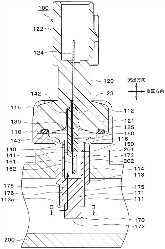
[0036] Hereinafter, a first embodiment will be described with reference to the drawings. The pressure temperature sensor of this embodiment can detect both the pressure and the temperature of the measurement medium. The pressure and temperature sensor is fixed to the piping, and detects the pressure and temperature of the measurement medium in the piping. The measurement medium is, for example, refrigerant used in automobiles. The measurement medium also includes lubricating oil such as engine oil and transmission oil, and gas.

[0037] Such as figure 1 As shown, the pressure temperature sensor 100 includes a housing 110 , a sensor body 120 , a potting portion 130 , a molded resin portion 140 , a sensor chip 150 and an introduction portion 170 .

[0038] The housing 110 is a hollow shell formed by machining a metal material such as SUS by cutting or the like. The housing 110 has a protruding portion 111 on one end side and an opening portion 112 on the other end side. The...

no. 2 Embodiment approach

[0076] In this embodiment, differences from the first embodiment will be described. Such as Figure 12 As shown, the introduction portion 170 has a planar tapered surface 180 . The blade surface 174 of the blade 175 and the fixed surface 177 of the base 172 are connected at the tapered surface 180 . This makes it possible to easily move the measurement medium entering the acute-angle portion formed by the adjacent blades 175 toward the sensor chip 150 along the tapered surface 180 .

[0077] As a variant, such as Figure 13 As shown, the introduction portion 170 may have a curved surface 181 . The curved surface 181 is a curved surface that is recessed toward the corner connecting the blade surface 174 of the blade 175 and the fixing surface 177 of the bottom 172 .


PUM


Abstract

A pressure / temperature sensor includes a sensor part (150) having a pressure detection unit (152) that detects the pressure of a medium to be measured and a temperature detection unit (152) that detects the temperature of the medium. The pressure / temperature sensor includes holding parts (110, 120, 130) each of which has a tube part (113) and holds the sensor part so that the sensor part is positioned inside the tube part and in which the tube part is fixed to piping (200) to which the tube part is to be attached. The pressure / temperature sensor includes an introduction part (170) that is provided to the holding part so as to be positioned more inside the piping than the sensor part and that is positioned inside the piping through fixing of the tube part to the piping. The introduction part includes a plurality of blades (175) that have blade surfaces (174) parallel to the projection direction of the introduction part with respect to the sensor part. The blades are radially arranged ona perpendicular surface perpendicular to the projection direction, and angles formed between the blade surfaces of adjacent blades are all acute.

Description

[0001] Cross-reference of related applications [0002] This application is based on Japanese Patent Application No. 2018-135706 filed on July 19, 2018, the contents of which are cited here. technical field [0003] The invention relates to a pressure temperature sensor for detecting the pressure and temperature of a measuring medium. Background technique [0004] Conventionally, for example, Patent Document 1 proposes a sensor for detecting the pressure and temperature of a measurement medium. The sensor includes a diffuser protruding from the tubular mouth. The diffuser includes 4 vanes extending the length of the tubular mouth. The four blades are arranged at equal angles in the circumferential direction centering on the axis along the longitudinal direction. That is, in the circumferential direction, the angle formed by adjacent blades is 90°. The measuring medium is introduced into the tubular opening along the blade face of the blade of the diffuser. [0005] prio...

Claims


Application Information

Patent Timeline
IPC IPC(8): G01K13/02G01K1/08G01L19/00G01D21/02
CPCG01K13/02G01D21/02G01L19/0092G01L19/0023G01L19/003G01K7/16G01L9/06
Inventor 金泽武村山亮介奥井阳一
Owner DENSO CORP
Features
  • R&D
  • Intellectual Property
  • Life Sciences
  • Materials
  • Tech Scout
  • Unparalleled Data Quality
  • Higher Quality Content
  • 60% Fewer Hallucinations
Learn More