Shearing device for tree root hair at road traffic stone
A technology of shearing device and curbstone, which is applied in the directions of roads, roads, cutting tools, etc., can solve the problems of laborious cutting work and high toughness, and achieve the effect of reducing the difficulty of manual work and the possibility of damage.
- Summary
- Abstract
- Description
- Claims
- Application Information
AI Technical Summary
Problems solved by technology
Method used
Image
Examples
Embodiment 1
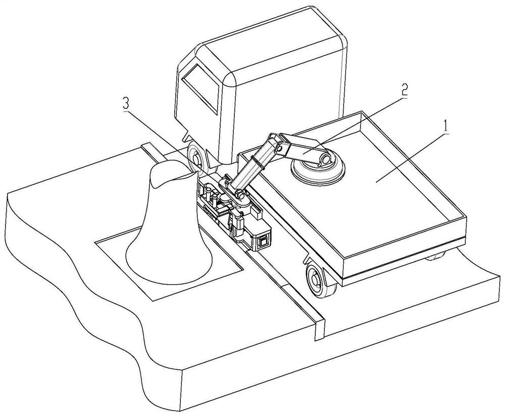
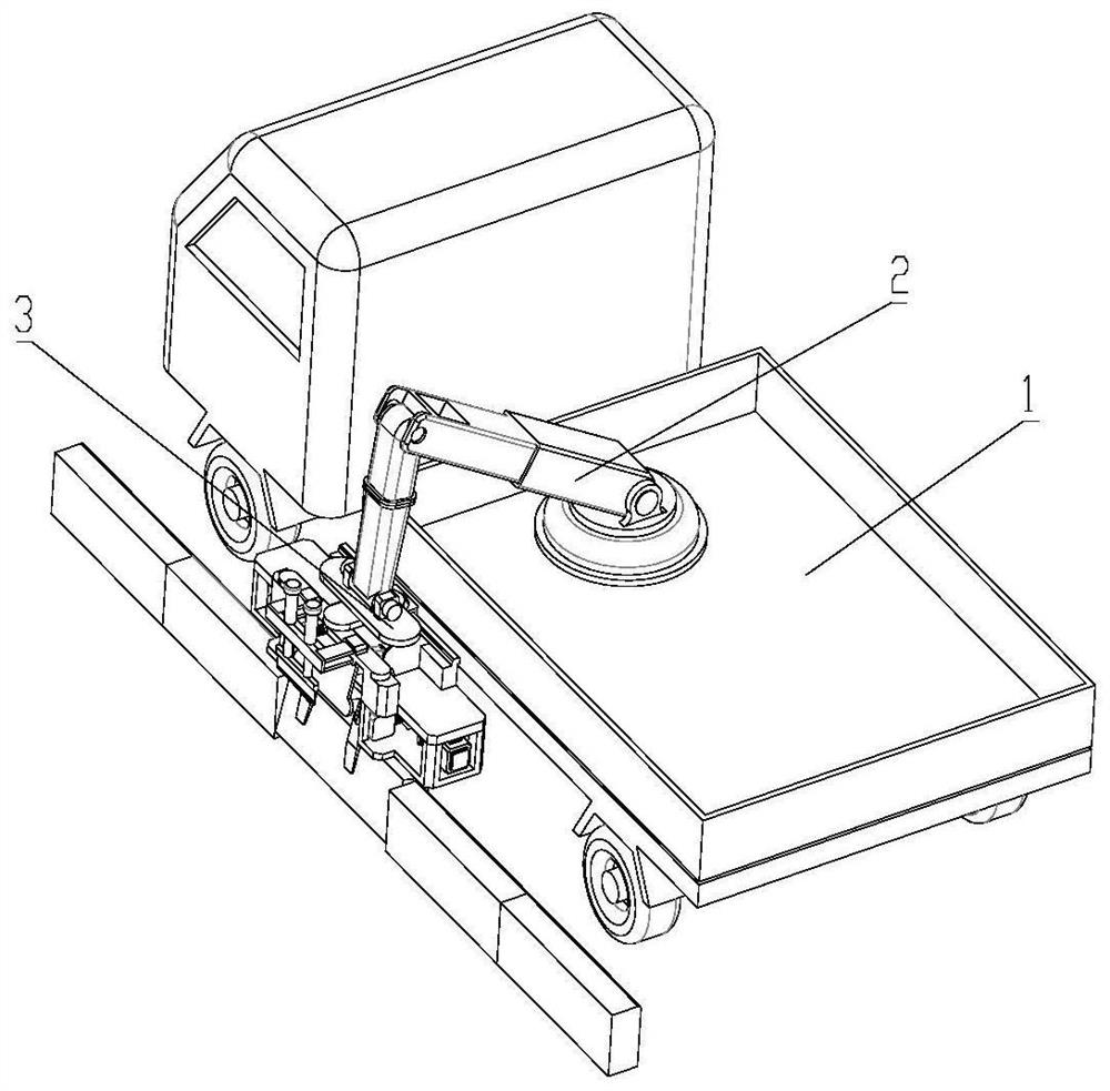
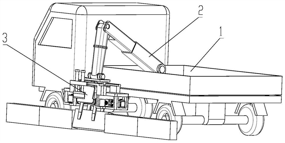
[0046] see Figure 1 to Figure 7 , the present invention provides a tree root hair cutting device at the curb, comprising a main support 31, the main support 31 is connected to a clamping assembly 32 and a shearing assembly 33;
[0047] The clamping assembly 32 includes a fixed splint 321 and a movable splint 322, and both sides of the fixed splint 321 are rotatably connected to the main bracket 31;
[0048] The cutting assembly 33 is arranged on the side towards the tree when the device works. The cutting assembly 33 includes a cutter 331, the upper side of the cutter 331 is fixedly connected to the movable end of the cutter push rod 332, and the fixed end of the cutter push rod 332 It is fixedly connected with the cutter bracket 333; the cutter bracket 333 is connected with the main bracket 31.
[0049] When this device is applied, it can be combined with the existing vehicle body 1 and the mechanical arm 2, and the shearing device 3 is connected to the end of the mechanica...
Embodiment 2
[0056] see Figure 8 to Figure 10 , on the basis of Embodiment 1, the outer side of the rotating shaft of the fixed splint 321 is sleeved with a limit ring 311, and the limit ring 311 is rotationally connected with the rotating shaft;
[0057] The limiting ring 311 is fixedly connected with the vibrating block 312. The side adjacent to the limiting ring 311 on the vibrating block 312 is fixedly provided with a vibrating rod 313. The axis of the vibrating rod 313 is perpendicular to the axis extension line of the limiting ring 311. The vibrating rod 313 runs through the limiting plate 314 and is slidably connected with the limiting plate 314. The limiting plate 314 is fixedly arranged on the lower support plate 315. The lower support plate 315 is a fixed part of the main support 31. One end of the vibrating rod 313 is fixed to the vibrating block 312. connected, the other end is fixedly connected to the vibrating plate 316; a vibrating spring 317 is arranged between the limitin...
Embodiment 3
[0064] see Figure 11 to Figure 15 , on the basis of the above embodiment, the side of the fixed splint 321 away from the movable splint 322 is fixedly connected to the supporting plate 325 through the connecting rod, and the supporting plate 325 extends toward the middle part of the fixed splint 321 away from the side of the two parallel parts;
[0065] When the device is in the cut-off state, the supporting plate 325 is horizontal, and the supporting plate 325 is located below the cutting knife 331 .
[0066] The weight of the parallel parts of the fixed splint 321 and the movable splint 322 is greater than that of the supporting plate 325 , and in a natural state, the supporting plate 325 is positioned upward.
[0067] The supporting plate 325 can support the tree roots from the lower side during the cutting operation, because the tree roots themselves have toughness, if only a cutting force is applied from the top, the roots will be pressed down, and it is difficult to com...
PUM
 Abstract
Description
Claims
Application Information
 - R&D Engineer
- R&D Manager
- IP Professional
- Industry Leading Data Capabilities
- Powerful AI technology
- Patent DNA Extraction
Browse by: Latest US Patents, China's latest patents, Technical Efficacy Thesaurus, Application Domain, Technology Topic.
© 2024 PatSnap. All rights reserved.Legal|Privacy policy|Modern Slavery Act Transparency Statement|Sitemap


