Automatic printing paper waste discharging device

A technology of automatic discharge and paper waste, applied in the field of papermaking, can solve the problems that the sundries cannot be cleaned in time, the dust cannot be completely separated, and it is unfavorable for long-term use, etc., and achieves the effect of ensuring air passage, low use cost, and convenient cleaning.

Inactive Publication Date: 2021-03-02
枣庄市天龙纸业有限公司
View PDF3 Cites 1 Cited by
  • Summary
  • Abstract
  • Description
  • Claims
  • Application Information

AI Technical Summary

Problems solved by technology

[0003] In the prior art, printing paper produces a lot of waste during the production process, and the waste in the prior art is generally directly disposed of by discharging, which will pollute the environment and is not conducive to environmental protection
At present, there are also equipments on the market that have the function of separating waste, but the fine waste and the dust mixed in it cannot be completely separated, and the separated sundries cannot be cleaned in time, which is not conducive to long-term use. Therefore, the existing The printing paper waste discharge device is improved to solve the above problems

Method used


Image

  • Automatic printing paper waste discharging device
  • Automatic printing paper waste discharging device
  • Automatic printing paper waste discharging device

Examples


Embodiment 1

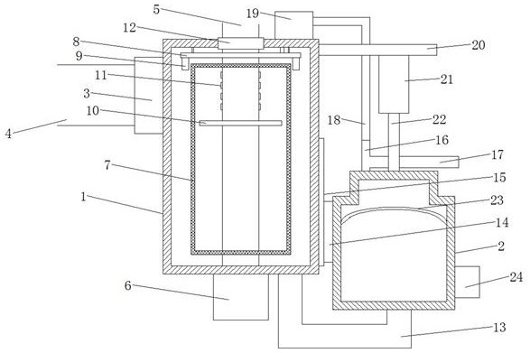
[0020] Please refer to the figure, in the embodiment of the present invention, an automatic printing paper waste discharge device includes a housing 1, a water tank 2, a suction fan 3, an air inlet pipe 4, and an air outlet pipe 5; on the top of the housing 1 It is connected with an air intake pipe 4, and a material suction fan 3 is installed in the air intake pipe 4, and the air with waste is sucked into the housing 1; the bottom of the housing 1 is coaxially fixed with a vertical motor 6, and the motor The output shaft of 6 extends upwards into the housing 1, and the output shaft of the motor 6 is coaxially fixed with a vertical air outlet pipe 5, and the upper end of the air outlet pipe 5 stretches out from the top of the housing 1, and The bearing 12 is rotatably connected with the casing 1 , so that the filtered air is discharged upward from the top of the air outlet pipe 5 .

[0021] Inside the housing 1, there is a separation mesh cylinder 7 fixed on the outside of the ...

Embodiment 2

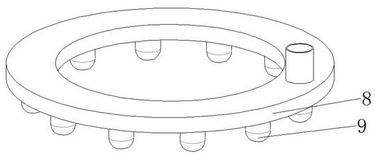
[0024] On the basis of Embodiment 1, the top of the water tank 2 is communicated with a three-way pipe 16, and one end of the three-way pipe 16 is communicated with an overflow pipe 17 that is flush with the top of the water tank 2. When the water tank 2 moves downward, the excess The water is discharged from the water tank 2, and the other end of the tee pipe 16 is connected to the circulation pump 19 through the circulation pipe 18. The material of the circulation pipe 18 is the same as that of the drain pipe 13. A part of the water inside is pumped into the water spray pipe 8, so that a part of the water circulates and flows, reducing the consumption of water.

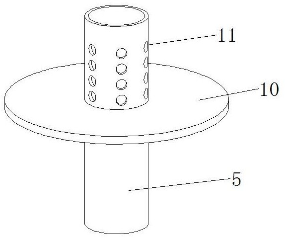
[0025] During use, the air with waste enters into the housing 1 from the air intake pipe 4, contacts with the rotating separation net cylinder 7, and after being filtered by the separation net cylinder 7, the air enters from the air inlet hole 11 in the separation net cylinder 7. Exhausted from the air outlet pipe 5...


PUM


Abstract

The invention relates to the field of papermaking, and particularly discloses an automatic printing paper waste discharging device which comprises a shell, a water tank, a suction fan, an air inlet pipe and an air outlet pipe. A separation net cylinder fixed to the outer side of the air outlet pipe is arranged in the shell, and a plurality of air inlet holes are evenly formed in the side wall, corresponding to the top end in the separation net cylinder, of the air outlet pipe. The lower side of a water spraying pipe is uniformly communicated with a plurality of vertical nozzles; the bottom ofthe water tank is communicated with the bottom of the shell through a drain pipe; a sliding seat is slidably connected to the sliding rail; and a filter screen is fixedly mounted in the water tank. Waste is separated from air by arranging the rotary separation net barrel in the shell and flushed under the action of downward water spraying, so that the waste is mixed into water, and the air passingability of the separation net barrel is guaranteed; sewage with waste enters the water tank from the bottom, the water tank moves up and down, and internal water is discharged according to differentheights of the water tank.

Description

technical field [0001] The invention relates to the field of papermaking, in particular to an automatic discharge device for printing paper waste. Background technique [0002] A general term for paper used for various printed matter. Such as letterpress printing paper, offset printing paper, high-grade glossy cardboard, newsprint, writing paper, etc. It is characterized by good printing adaptability and high opacity. [0003] In the prior art, printing paper produces a lot of waste in the production process, and the waste in the prior art is generally directly disposed of by discharging, which will pollute the environment and is not conducive to environmental protection. At present, there are also equipments on the market that have the function of separating waste, but the fine waste and the dust mixed in it cannot be completely separated, and the separated sundries cannot be cleaned in time, which is not conducive to long-term use. Therefore, the existing The printing p...

Claims


Application Information

Patent Timeline
Patent Type & Authority Applications(China)
IPC IPC(8): B01D46/24B01D46/00B01D33/01
CPCB01D46/2411B01D33/015B01D46/70
Inventor 秦启文秦政刘成华韩绪峰胡中理
Owner 枣庄市天龙纸业有限公司
Why Eureka
Try Eureka