
Adjustable cutting device for building construction

A technology for construction and cutting devices, applied in sawing machine devices, manufacturing tools, metal sawing equipment, etc., can solve the problems of inability to adjust the angle of the tool, hidden dangers, unstable placement, etc., to achieve easy storage, increased applicability, and use. outstanding effect

Inactive Publication Date: 2021-03-02
曹传辉
View PDF0 Cites 0 Cited by
  • Summary
  • Abstract
  • Description
  • Claims
  • Application Information

AI Technical Summary

Problems solved by technology

[0003] Cutting tools are often used in construction projects. Most of the existing cutting devices have a fixed position of the cutter shaft. However, in reality, for some slits or the installation requirements of the interface of the board, because the angle of the cutter cannot be adjusted, the device needs to be manually operated frequently. Adjust and correct the cutting angle. At the same time, the knives are mostly exposed, and there are certain safety hazards if they are unstable when placed.

Method used


Image

  • Adjustable cutting device for building construction
  • Adjustable cutting device for building construction
  • Adjustable cutting device for building construction

Examples


Embodiment 1

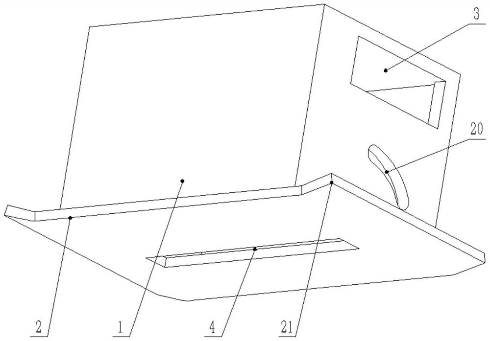
[0025] Example 1: Please refer to figure 1 , an adjustable cutting device for building construction, comprising a box body 1 and a slide plate 2, the bottom of the box body 1 is an open structure, the slide plate 2 is fixedly connected below the box body 1, and an operation port 3 is opened on the right side wall of the box body 1 , the slide plate 2 is provided with a knife slot 4;

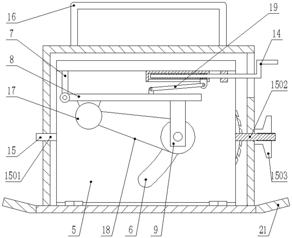
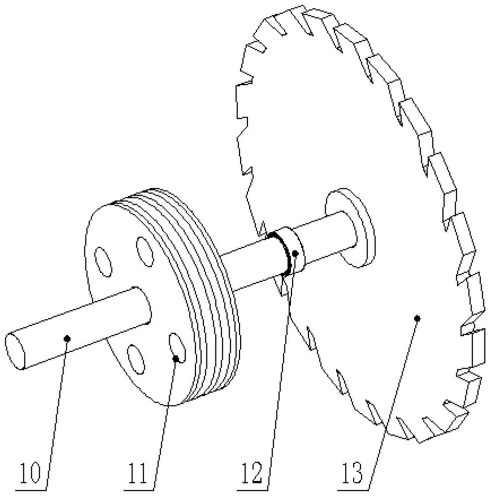
[0026] see figure 2 , the top of the slide plate 2 is hinged with a mounting frame 5, the mounting frame 5 is located on the front side of the knife slot 4 inside the box body 1, the rear wall of the mounting frame 5 is provided with a second arc-shaped groove 6, and the top of the mounting frame 5 is fixedly connected. There is a support plate 7, the lower end of the support plate 7 is fixedly rotatably connected with a mounting plate 8, and the lower end of the mounting plate 8 is fixedly welded with a support block 9, and the support block 9 is rotatably connected with a rotating shaft 10, ...

Embodiment 2

[0041] Embodiment 2: This embodiment is a further improvement on the previous embodiment: please refer to Figure 1-2 , the left and right ends of the slide plate 2 are fixedly connected with seesaws 21, and the joints of the seesaw 21 and the slide plate 2 are rounded.

[0042]The working principle of the present invention is: when the device is working, shake the manual screw 1403 to change the leftward movement of the slider 1404 in the slide seat 1401, and through the action of the connecting rod 19, the mounting plate 8 is rotated, and the rotating shaft 10 passes through the bearing 12 and The second arc groove 6 is slidingly connected, and the cutter wheel 13 follows the position change of the rotating shaft 10, protruding from the knife outlet groove 4 on the slide plate 2, and then the motor 17 is started, and the rotating shaft 10 is driven by the belt 18 to rotate, so that the cutter wheel 13 For cutting work, the cutter wheel 13 can be retracted by shaking the manu...


PUM


Abstract

The invention discloses an adjustable cutting device for building construction, and relates to the technical field of cutting devices for building construction. The adjustable cutting device comprisesa box body and a sliding plate, the bottom of the box body is of an open type structure, the sliding plate is fixedly connected to the lower portion of the box body, an operation opening is formed inthe right side wall of the box body, a cutter outlet groove is formed in the sliding plate, and a mounting frame is rotatably hinged to the upper portion of the sliding plate; and a cutter retractingmechanism is fixedly connected to the mounting frame, and angle adjusting mechanisms are arranged at the two sides of the mounting frame. Compared with the prior art, the adjustable cutting device has the beneficial effects that the position of a sliding block is adjusted through a manual lead screw, so that a mounting plate rotates, a rotating shaft slides in a second arc-shaped groove, a cutterwheel extends out of a cutter outlet groove under the action of the cutter retracting mechanism, the distance of the cutter wheel extending out of the sliding plate can be adjusted according to requirements by means of the manner, and the cutting depth can be adjusted; and after the device is used, the knife wheel is retracted through the knife retracting mechanism, the device is more convenientto store, and the device with the knife wheel capable of being hidden is safer.

Description

technical field [0001] The invention relates to the technical field of building construction cutting devices, in particular to an adjustable cutting device for building construction. Background technique [0002] The function of the construction industry is mainly to carry out construction and installation activities for various building materials and components, machinery and equipment, and to build productive and non-productive fixed assets for the national economy. The development of the construction industry has a very close relationship with the scale of investment in fixed assets, and they promote and restrict each other. [0003] Cutting tools are often used in construction projects. Most of the existing cutting devices have a fixed position of the cutter shaft. However, in reality, for some slits or the installation requirements of the interface of the board, because the angle of the cutter cannot be adjusted, the device needs to be manually operated frequently. Adj...

Claims


Application Information

Patent Timeline
Patent Type & Authority Applications(China)
IPC IPC(8): B23D47/00B23D47/02B23D47/12B23Q1/25B23Q11/06
CPCB23D47/00B23D47/02B23D47/12B23Q1/25B23Q11/06
Inventor 曹传辉
Owner 曹传辉
Learn More