
A cable stripping machine

A stripping machine and cable technology, applied in the direction of disassembling/armoring cable equipment, etc., can solve problems such as poor stripping effect, and achieve the effect of good cutting effect, increasing friction and reducing resistance

Active Publication Date: 2020-07-24
金华八达集团有限公司 +1
View PDF3 Cites 0 Cited by
  • Summary
  • Abstract
  • Description
  • Claims
  • Application Information

AI Technical Summary

Problems solved by technology

[0004] The purpose of the invention is to provide a cable stripping machine with good stripping effect in order to overcome the disadvantage of poor stripping effect in the prior art

Method used


Image

  • A cable stripping machine
  • A cable stripping machine
  • A cable stripping machine

Examples


Embodiment Construction

[0022] In conjunction with the accompanying drawings and specific embodiments, the present invention is further elaborated:

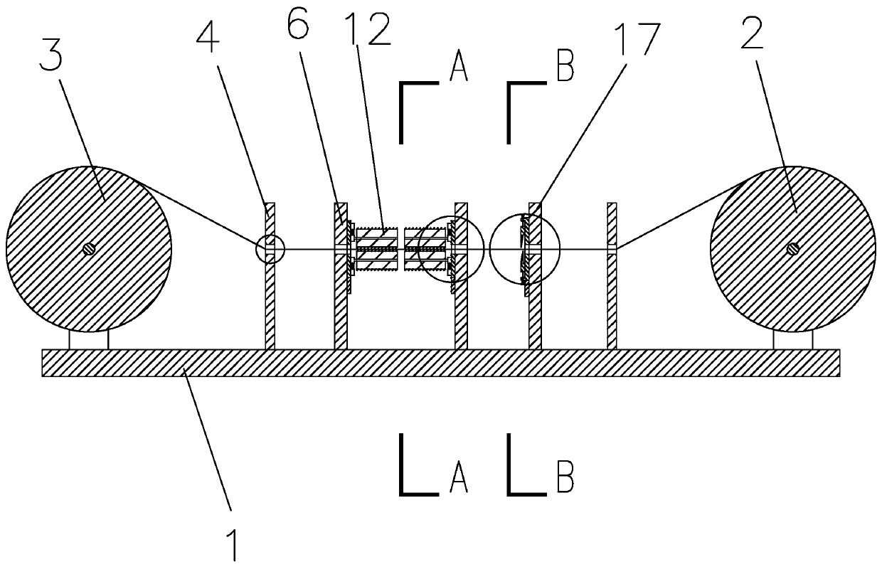
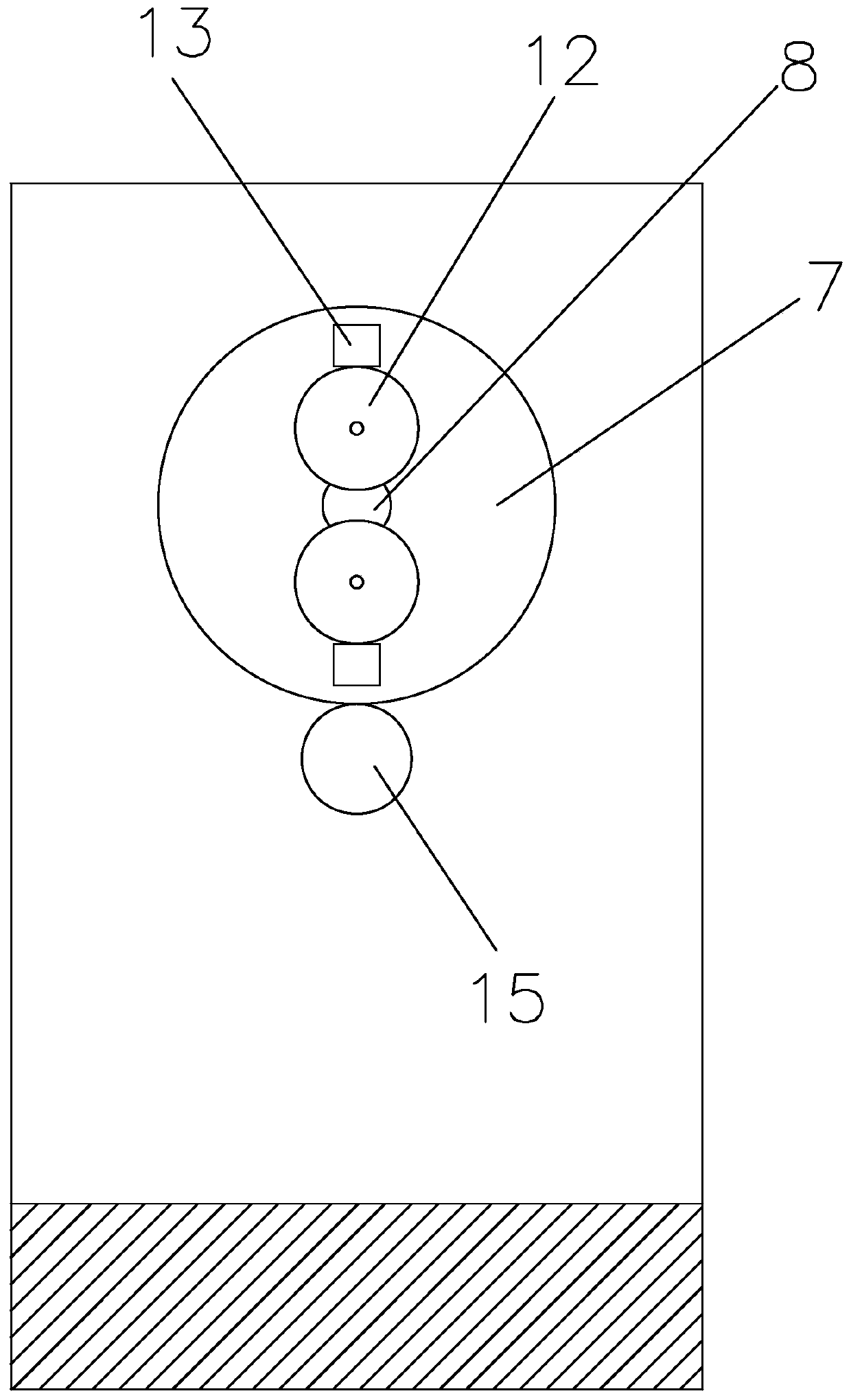
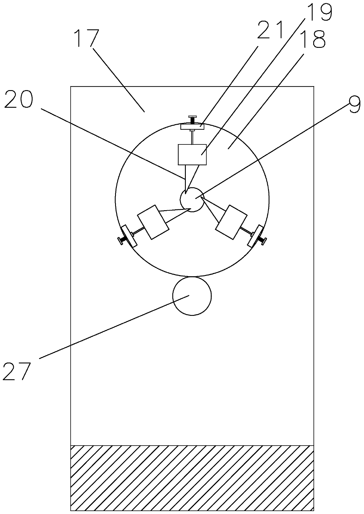
[0023] figure 1 , figure 2 and Figure 4 It is a cable stripping machine, including a base 1, one end of the base 1 is rotatably connected to a wire feed roller 2, and the other end of the base 1 is rotatably connected to a take-up roller 3, and the connection between the wire feed roller 2 and the take-up roller 3 There are two positioning plates 4 that are arranged oppositely, and a positioning hole 5 is provided on the positioning plates 4. The positioning plates 4 are fixed on the base 1, and a positioning plate is formed between the positioning plates 4. 4. A cutting device, a wire twisting device and another wire twisting device are sequentially provided in the direction of the other positioning plate 4. The cutting device is located on the side of the twisting device close to the wire feeding roller 2. The cutting device and the wire twisting ...


PUM


Abstract

The invention discloses a cable stripping machine, and relates to the field of cable processing. The cable stripping machine comprises a base, one end of the base is rotatably connected with a wire feeding roller, the other end of the base is rotatably connected with a wire collecting roller, two positioning plates are arranged between the wire feeding roller and the wire collecting roller, each positioning plate is provided with a positioning hole, a cutting device, a wire twisting device and another wire twisting device are arranged between the positioning plates, the wire twisting device comprises a wire twisting support and a wire twisting gear, first cable through holes are formed in the circle center of the wire twisting gear and on the wire twisting support, two first sliding blocksare slidably connected onto the wire twisting gears, one side of the first sliding block is fixedly connected with a rotating shaft, the rotating shaft is rotatably connected with a damping roller coaxial with the rotating shaft, one side, far away from the other first sliding block, of any first sliding block is provided with a first spring and a first bump, one side of the wire twisting gear ismeshed with a first driving gear, and the surface of the damping roller is provided with a spiral bulge; and the cable stripping machine has good stripping effect.

Description

technical field [0001] The invention belongs to the field of cable processing, in particular to a cable stripping machine. Background technique [0002] In the process of production maintenance or equipment installation, it is often necessary to strip off a section of the plastic outer layer of the cable for wiring, or to strip the discarded cable, etc. Most people use stripping pliers, electrician's knife or other blades. This simple tool not only has low working efficiency, but also easily scratches hands or other parts of the body. Especially when the wiring workload is relatively large and there are many cables, this simple tool cannot meet the needs of the market. [0003] National patent authorization announcement number CN201741979U, authorization announcement date 20110209, discloses "a cable stripping machine"; includes a frame, a wire entry device, a cutting device and a pulling device, and the cutting device and the pulling device are sequentially arranged on the ...

Claims


Application Information

Patent Timeline
Patent Type & Authority Patents(China)
IPC IPC(8): H02G1/12
Inventor 孔晓峰贺燕钱新建陈跃国张文杰施安张晓途刘歆
Owner 金华八达集团有限公司
Learn More