Steel structure bridge box welding positioning device

A welding positioning and steel structure technology, applied in welding equipment, auxiliary devices, welding equipment, etc., can solve the problems of unstable welding quality, spatter, and large environmental impact, reduce welding difficulty and strength, and improve the accuracy of return performance, improve welding accuracy

Pending Publication Date: 2021-03-02
张国学
View PDF0 Cites 0 Cited by
  • Summary
  • Abstract
  • Description
  • Claims
  • Application Information

AI Technical Summary

Problems solved by technology

[0002] The code plate of the steel structure bridge is an indispensable auxiliary tool for the on-site processing of the steel bridge. The code plate fixes the position of two adjacent beam sections to be welded, fits the plane line shape of the bridge, and positions the beam section on site before welding. When domestic production units process steel structure bridges, the code boards are generally processed from waste materials, fixed and fully welded between two adjacent boxes, and carbon dioxide gas shielded welding is used to weld the two adjacent boxes. Remove the code plate and grind the surface of the box body. This method is time-consuming and material-intensive. Moreover, when welding with a carbon dioxide gas welding device, it is easy to cause problems such as spatter and poor forming, resulting in unstable welding quality and greater environmental impact.

Method used


Image

  • Steel structure bridge box welding positioning device
  • Steel structure bridge box welding positioning device
  • Steel structure bridge box welding positioning device

Examples


Embodiment

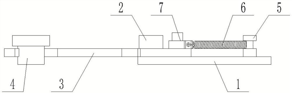
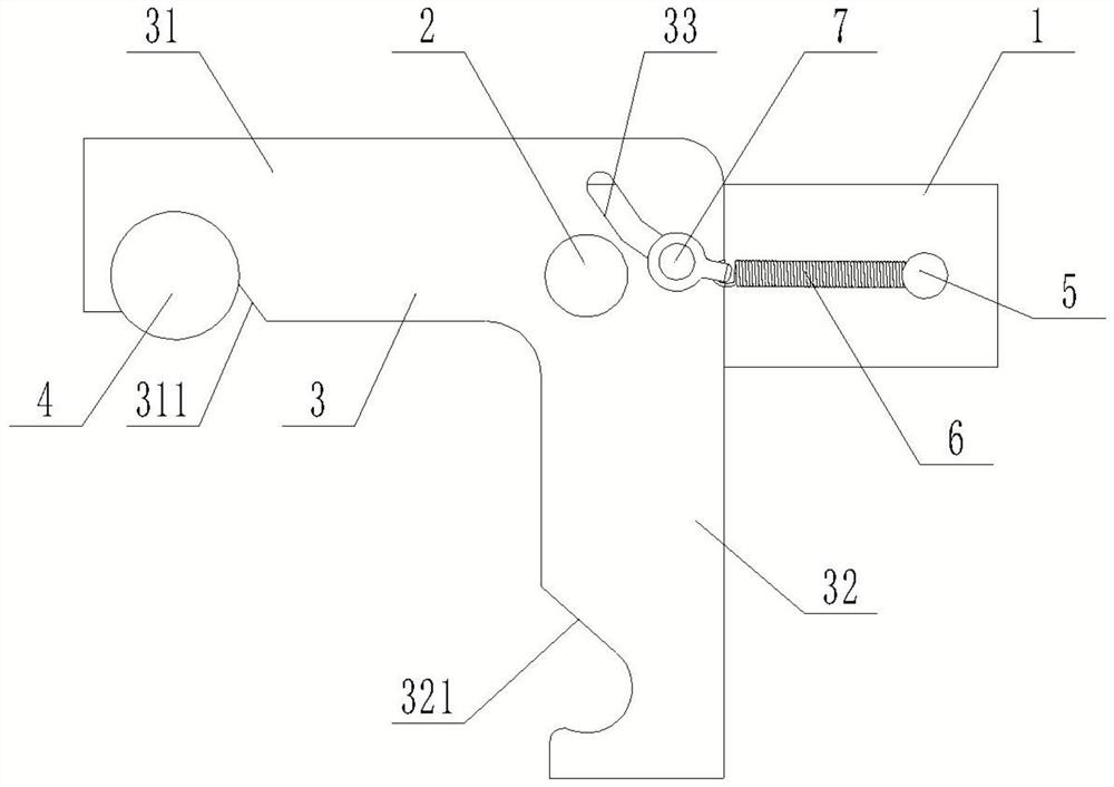
[0024] Such as Figure 1-Figure 4 As shown, a steel structure bridge box welding positioning device includes a rectangular positioning plate 1 arranged along the extension direction of the weld seam. One end of the positioning plate 1 in the length direction is connected to a rotating shaft 2, and the rotating shaft 2 is sleeved with a The movable baffle 3 that the shaft 2 rotates, the movable baffle 3 includes a first baffle 31 and a second baffle 32, the first baffle 31 and the second baffle 32 are L-shaped, and the L-shaped cavity is along the positioning plate 1 The limit block 4 is arranged in the length direction, the rotating shaft 2 is located at the junction of the first baffle 31 and the second baffle 32, the movable baffle 3 is parallel to the ground, and the end of the positioning plate 1 in the length direction away from the rotating shaft 2 is provided with a return fixing A return spring 6 is connected between the rod 5 and the return fixed rod 5 and the movable...


PUM


Abstract

The invention discloses a steel structure bridge box welding positioning device which comprises a rectangular positioning plate arranged in the welding seam extending direction, a rotating shaft is connected to one end of the positioning plate in the length direction, and a movable baffle capable of rotating around the rotating shaft is arranged on the rotating shaft in a sleeving manner and comprises a first baffle and a second baffle. The first baffle and the second baffle are in an L shape, a limiting block is arranged in an L-shaped cavity in the length direction of the positioning plate,the rotating shaft is located at the joint of the first baffle and the second baffle, the movable baffle is parallel to the ground, a return fixing rod is arranged at the end, away from the rotating shaft, of the positioning plate in the length direction, and a return spring is connected between the return fixing rod and the movable baffle. When a welding machine moves along a welding seam, the movable baffle is pushed to rotate, after the welding machine passes through the movable baffle, the rotated movable baffle automatically resets under the action of the spring, and the welding accuracyand the welding seam quality can be effectively improved.

Description

technical field [0001] The invention relates to the field, in particular to a steel structure bridge box welding positioning device. Background technique [0002] The code plate of the steel structure bridge is an indispensable auxiliary tool for the on-site processing of the steel bridge. The code plate fixes the position of two adjacent beam sections to be welded, fits the plane line shape of the bridge, and positions the beam section on site before welding. When domestic production units process steel structure bridges, the code boards are generally processed from waste materials, fixed and fully welded between two adjacent boxes, and carbon dioxide gas shielded welding is used to weld the two adjacent boxes. Remove the code plate and grind the surface of the box body. This method is time-consuming and material-intensive. Moreover, when welding with a carbon dioxide gas welding device, it is easy to cause problems such as spatter and poor forming, resulting in unstable we...

Claims


Application Information

Patent Timeline
Patent Type & Authority Applications(China)
IPC IPC(8): B23K9/18B23K9/12B23K9/32B23K37/04
CPCB23K9/12B23K9/18B23K9/32B23K37/0426
Inventor 张国学杨雪艳荆帅
Owner 张国学
Why Eureka
Try Eureka