Timber cutting machine

A wood cutting machine, intermediate position technology, applied in sawing equipment, wood processing appliances, circular saws, etc., can solve problems such as damage to wood, jitter, etc.

Pending Publication Date: 2021-03-02
杨蒙恩
View PDF1 Cites 0 Cited by
  • Summary
  • Abstract
  • Description
  • Claims
  • Application Information

AI Technical Summary

Problems solved by technology

[0006] In order to solve the technical problems in the background technology, the present invention proposes a wood cutting machine, which solves the problem that it is difficult to cut different positions of the same wood, and the wood is easily damaged due to vibration during cutting

Method used


Image

  • Timber cutting machine
  • Timber cutting machine
  • Timber cutting machine

Examples


Embodiment 1

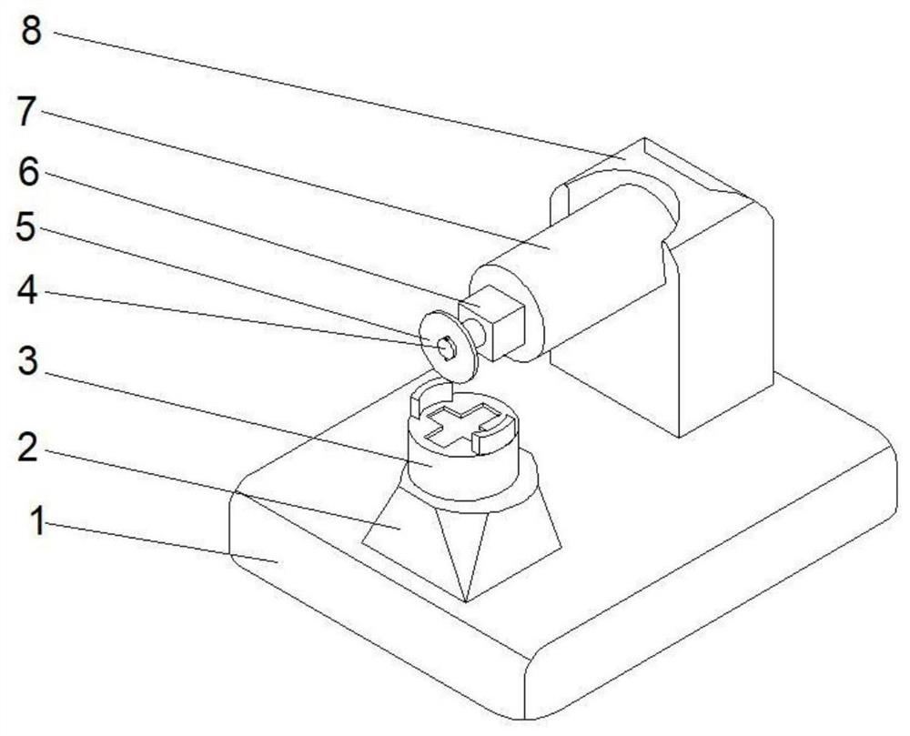
[0035] Such as Figure 1-2 , a wood cutting machine proposed by the present invention, comprising a base 1, a column 8 is fixedly connected to the middle position on the top right side of the base 1, and a force arm 7 is arranged on the left side of the top of the column 8, and the force arm 7 is far away from the middle position of one end of the column 8 A motor 6 is fixedly connected, and the output shaft of the motor 6 is rotatably connected to a connector 4. The outer surface of the connector 4 is fixedly connected to a cutter 5. An adjustment device 2 is arranged at the middle position on the left side of the top of the base 1, and the top of the adjustment device 2 is fixed. A connecting device 3 is connected.

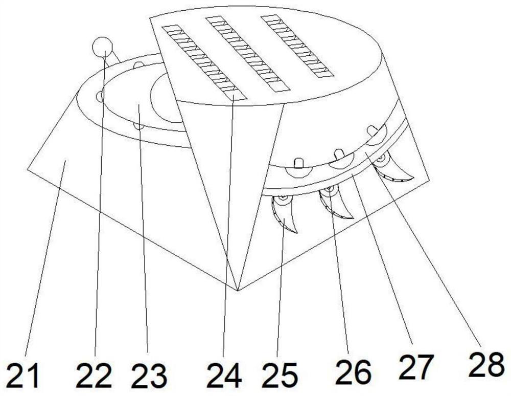
[0036] Wherein, the adjustment device 2 includes an outer frame 21, a connecting groove 24 is opened in the middle of the top of the outer frame 21, a rotating rod 22 is arranged in the left middle part of the outer frame 21, and an adjusting rod 22 is arranged ...

Embodiment 2

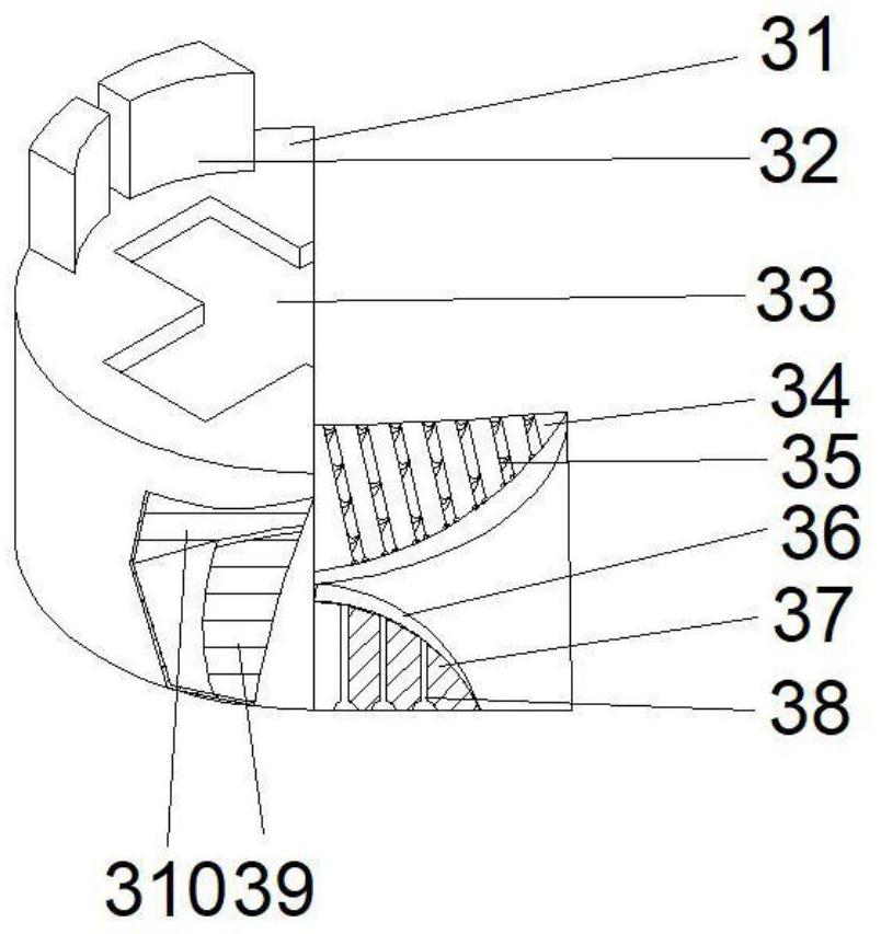
[0039] Such as Figure 1-6 As shown, on the basis of Embodiment 1, the present invention provides a technical solution: the connection device 3 includes an outer frame 31, a groove 33 is opened in the middle of the top of the casing 31, and the top of the casing 31 is located on both sides of the groove 33 A stopper 32 is provided, a plate 38 is fixedly connected to the middle position of the bottom of the inner cavity of the shell 31, and a display plate 36 is fixedly connected to the top of the plate 38. The middle of the bottom of the inner cavity of the shell 31 is located on both sides of the plate 38 and a guide cavity 36 is provided. The middle of the inner cavity bottom of the housing 31 is located on the left side of the display board 36 and is fixedly connected with a side plate 39, and the top of the side board 39 is fixedly connected with a top board 310, and the top of the display board 36 is provided with a swing plate 35, and the inside of the swing plate 35 is p...

Embodiment 3

[0042] Such as Figure 1-6 As shown, on the basis of Embodiment 1 and Embodiment 2, the present invention provides a technical solution: the top of the inner cavity of the frame 28 is provided with a guide block 283, and the top of the guide block 283 penetrates the frame 28 and extends to the outside of the frame 28 The top of the inner chamber of the frame 28 is fixedly connected with push blocks 282 on both sides of the guide block 28 , and the bottom of the frame 28 is located on both sides of the push block 282 and is provided with circumscribed balls 281 .

[0043] Wherein, the adjustment ring 23 includes a connecting ring 231, the inner surface of the connecting ring 231 is provided with a connecting block 232, the top of the connecting block 232 penetrates the connecting ring 231 and extends to the inside of the connecting ring 231, and the connecting block 232 is fixedly connected to one end away from the connecting ring. Force plate 233 is arranged.

[0044] Wherein...


PUM


Abstract

The invention discloses a timber cutting machine. The timber cutting machine comprises a base; a stand column is fixedly connected to the middle of the right side of the top of the base; a force arm is arranged on the left side of the top of the stand column; a motor is fixedly connected to the middle of the end, away from the stand column, of the force arm; an output shaft of the motor is rotationally connected with a connector; and a cutter is fixedly connected to the outer surface of the connector; an adjusting device is arranged in the middle of the left side of the top of the base; and aconnecting device is fixedly connected to the top of the adjusting device. The timber cutting machine relates to the technical field of timber processing. According to the timber cutting machine, theadjusting device rotates at the top of the base to conduct rotary adjustment, before work, the adjusting device conducts adjustment and then is fixed, different positions of the same timber are cut, the situation that the timber is prone to damage due to shaking during cutting is avoided, and due to the arrangement of a side plate and a top plate, a shell have large bearing force before and afterwork; therefore, a heavier object is further supported, and the device is not prone to deformation.

Description

technical field [0001] The invention relates to the technical field of wood processing, in particular to a wood cutting machine. Background technique [0002] Wood is a material widely used in daily life. Because wood has natural beautiful patterns, luster and colors, it can play a special decorative effect, and it can also give people a sense of warmth and security. It is generally used in the manufacture of various Furniture, in the traditional wood processing technology, wood cutting is an important part of making wood products. Wood has the advantages of light weight, high strength ratio, good elasticity, impact resistance, rich and beautiful texture and color, and easy processing. Resource regeneration, wood has played an important role in the national economy since ancient times. [0003] According to a wood cutting machine disclosed in Chinese Patent No. CN111571726A, the wood can be cut into cross-sections with different angles by simultaneously adjusting the angles...

Claims


Application Information

Patent Timeline
Patent Type & Authority Applications(China)
IPC IPC(8): B27B5/02B27B29/02B27B5/29
CPCB27B5/02B27B5/29B27B29/02
Inventor 杨蒙恩
Owner 杨蒙恩
Why Eureka
Try Eureka