Wake flow calculation method considering local environmental factors of wind power plant

A technology of environmental factors and calculation methods, applied in wind power generation, complex mathematical operations, etc., can solve problems such as inaccurate calculation of model parameters, difficulty in obtaining turbulence intensity, unreasonable correlation between model parameters and flow direction turbulence intensity, etc., to improve accuracy , the effect of expanding the scope of application

Active Publication Date: 2021-03-02
HUANENG CLEAN ENERGY RES INST +1
2 Cites 1 Cited by

AI-Extracted Technical Summary

Problems solved by technology

[0003] From the above analysis, it can be seen that the wake expansion radius in the Gaussian wake model needs to be determined by empirical formulas. It is generally believed that the model parameters included in the wake expansion radius are related to the flow turbulence intensity, while the wind turbine wake is mainly in the vertical direction. direction and ...

Abstract

The invention discloses a wake flow calculation method considering local environmental factors of a wind power plant, and belongs to the technical field of wind turbine generator wake flow calculation. Firstly, local environment parameters of a wind power plant are obtained according to the local environment of the wind power plant, then an atmospheric stability function of the environment where the wind power plant is located is calculated, the obtained atmospheric stability function serves as input, and the earth surface friction speed is calculated through the MoninObukhov similarity theory. Then sequentially calculating to obtain the flow velocity pulsation of the near-stratum, the flow turbulence intensity of the near-stratum and the spanwise turbulence intensity of the near-stratum,and establishing a direct proportion relationship between the spanwise turbulence intensity of the hub height and the spanwise turbulence intensity of the near-stratum to obtain the spanwise turbulence intensity of the hub height; sequentially calculating to obtain a wake flow expansion coefficient, an initial wake flow radius and a wake flow radius, calculating a wake flow region speed loss thickness, and finally obtaining the speed distribution of the wake flow region. According to the method, the application range of the wake flow calculation method is greatly expanded, and the accuracy ofa calculation result is improved.

Application Domain

Wind energy generationComplex mathematical operations

Technology Topic

MeteorologySimilarity theory +3

Image

  • Wake flow calculation method considering local environmental factors of wind power plant
  • Wake flow calculation method considering local environmental factors of wind power plant
  • Wake flow calculation method considering local environmental factors of wind power plant

Examples

  • Experimental program(1)

Example Embodiment

[0040] The present invention will be further described in detail with the accompanying drawings and specific embodiments below, which are explanations rather than limitations of the present invention.
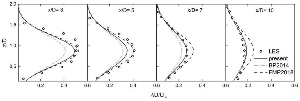
[0041] In order to verify the validity of the wake calculation method proposed by the present invention, the wake velocity distribution calculated by this method under different working conditions is compared with the large eddy simulation results reported in the literature and the wind tunnel experimental results, mainly comparing the wake expansion coefficient and velocity deficit distribution under different surface roughness and atmospheric stability conditions. The example data of the comparison of the present invention comes from reference [1].
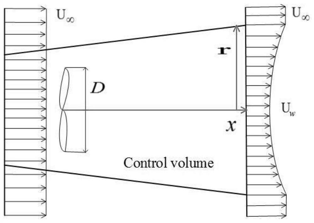
[0042] The present invention adopts figure 2 The control body shown, in accordance with figure 1 The steps shown build the wake calculation method. exist figure 2 in, U ∞ is the incoming flow velocity, U w is the velocity of the wake area, r is the distance from any point in the wake area parallel to the plane of the wind rotor to the height of the hub in the plane, and D is the diameter of the wind rotor.
[0043] The embodiment of the present invention is further described below with a specific example:
[0044] Step 1): Given the input parameter U ∞ =8.5m/s,z h =70m, D=80m, z 0 =0.05m, L=∞, φ=47°, C t = 0.8.
[0045] Step 2): From L=∞, we know that ζ=0, and substitute it into the atmospheric stability function to get ψ m (0)=0.
[0046] Step 3): Using the Monin-Obukhov similarity theory to calculate the surface friction velocity u * = 0.47m/s.
[0047] Step 4): Use the empirical formula to calculate the magnitude of the flow velocity fluctuation σ in the near-surface layer u,s =1.175m/s, and calculate the flow direction turbulence intensity I according to the definition u,s=0.138, the spanwise turbulence intensity I can be calculated further v,s = 0.11.
[0048] Step 5): according to the linear relational expression that the present invention proposes, get γ=1.0, can calculate I v,h = 0.11.
[0049] Step 6): Calculate the expansion coefficient of the wake calculation method according to the formula reported in the literature, and obtain k w = 0.025, ∈ = 0.293, and then we can calculate the change law of the wake radius with x
[0050] Step 7): According to the wake radius σ obtained in step 6), the velocity deficit in the wake region can be calculated which is image 3 The corresponding distribution law in .
[0051] image 3 The comparison between the velocity deficit in the wake region obtained by different wake calculation methods and the results of large eddy simulation is given. In the entire wake area, the velocity deficit predicted by the wake calculation method proposed by the present invention is closer to the large eddy simulation results, which is better than the BP2014 method and the FMP2018 method.
[0052] [1] Cheng W-C, Porté-Agel F.A simple physically-based model for wind-turbine wake growth in a turbulent boundary layer. Bound-Layer Meteorol 2018:1–10.
[0053] It should be noted that the above description is only a part of the embodiments of the present invention, and equivalent changes made according to the system described in the present invention are all included in the protection scope of the present invention. Those skilled in the art to which the present invention belongs can replace the described specific examples in a similar manner, as long as they do not deviate from the structure of the present invention or exceed the scope defined in the claims, they all belong to the protection scope of the present invention.

PUM

no PUM

Description & Claims & Application Information

We can also present the details of the Description, Claims and Application information to help users get a comprehensive understanding of the technical details of the patent, such as background art, summary of invention, brief description of drawings, description of embodiments, and other original content. On the other hand, users can also determine the specific scope of protection of the technology through the list of claims; as well as understand the changes in the life cycle of the technology with the presentation of the patent timeline. Login to view more.

Similar technology patents

Gamma-ray time detection device and manufacturing method of detector thereof

Owner:中国人民解放军第二炮兵装备研究院第六研究所

Reducing valve

InactiveCN103939624ALarge adjustable rangeExpand the scope of application
Owner:HANGZHOU WORLDWISE VALVE

Deep fluid diversion method

Owner:CHINA PETROLEUM & CHEM CORP +1

Classification and recommendation of technical efficacy words

  • improve accuracy
  • Expand the scope of application

Golf club head with adjustable vibration-absorbing capacity

InactiveUS20050277485A1improve grip comfortimprove accuracy
Owner:FUSHENG IND CO LTD

Stent delivery system with securement and deployment accuracy

ActiveUS7473271B2improve accuracyreduces occurrence and/or severity
Owner:BOSTON SCI SCIMED INC

Method for improving an HS-DSCH transport format allocation

InactiveUS20060089104A1improve accuracyincrease benefit
Owner:NOKIA SOLUTIONS & NETWORKS OY

Catheter systems

ActiveUS20120059255A1increase selectivityimprove accuracy
Owner:ST JUDE MEDICAL ATRIAL FIBRILLATION DIV

Gaming Machine And Gaming System Using Chips

ActiveUS20090075725A1improve accuracy
Owner:UNIVERSAL ENTERTAINMENT CORP

Method for converting flash animation data into hypertext markup language (HTML) 5 data

ActiveCN103176986AImprove conversion speedExpand the scope of application
Owner:SHANGHAI PATEO ELECTRONIC EQUIPMENT MANUFACTURING CO LTD

Robot system and interactive method

ActiveCN105598972ARealize multimodal interactionExpand the scope of application
Owner:BEIJING GUANGNIAN WUXIAN SCI & TECH
Why Eureka
Try Eureka