Current sharing circuit and method of thyristor alternating-current switch parallel circuit
A technology of AC switches and thyristors, which is applied in the field of current control of thyristors in parallel operation, can solve problems such as difficulty in implementation, high cost, and serious heat generation, and achieve good current sharing effect and high cost-effectiveness
- Summary
- Abstract
- Description
- Claims
- Application Information
AI Technical Summary
Problems solved by technology
Method used
Image


Examples
Embodiment 1
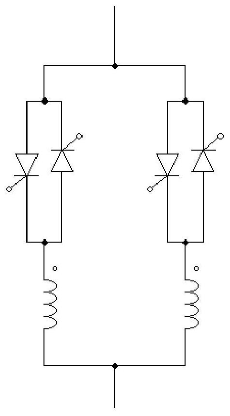
[0051] This embodiment is applicable to a thyristor AC switch parallel circuit with two parallel branches, a group of anti-parallel thyristors is connected between the input and output of each branch, the first group is SCR1, SCR3, and the second group is SCR2, SCR4. The anodes of SCR1 and SCR2 are connected to the input of the branch, and the cathode is connected to the output of the branch. We define it as a reverse thyristor. The anodes of SCR3 and SCR4 are connected to the output of the branch, and the cathode is connected to the input of the branch. We define it as a forward thyristor.
[0052] The current sharing circuit of this embodiment includes two transformers T1 and T2 corresponding to two branches, a drive unit 4 , a voltage detection unit 1 , a demagnetization detection circuit 2 , and a control circuit 3 .
[0053] Wherein, the primary side of each transformer is connected in series to a corresponding branch, and the primary side of the transformer is connected...
Embodiment 2
[0074] This embodiment discloses a current sharing method for a thyristor AC switch parallel circuit, which is implemented based on the circuit described in Embodiment 1. The method includes: when the demagnetization detection circuit 2 detects that the N transformers are demagnetized by the control circuit 3 , determine the thyristor to be turned on according to the voltage drop detected by the voltage detection unit 1, and control the driving unit 4 to drive the determined thyristor to turn on, specifically:
[0075] 1) The first logical AND circuit 31 outputs the comparison result output by the positive pressure detection circuit 11 and the output of the demagnetization detection circuit 2 to the R terminal of the RS flip-flop 35 after logical AND processing, and the second logical AND circuit 32 detects negative pressure The comparison result output by the circuit 12 and the output of the demagnetization detection circuit 2 are logically AND processed and output to the S te...
PUM
 Abstract
Description
Claims
Application Information
 - R&D
- Intellectual Property
- Life Sciences
- Materials
- Tech Scout
- Unparalleled Data Quality
- Higher Quality Content
- 60% Fewer Hallucinations
Browse by: Latest US Patents, China's latest patents, Technical Efficacy Thesaurus, Application Domain, Technology Topic, Popular Technical Reports.
© 2025 PatSnap. All rights reserved.Legal|Privacy policy|Modern Slavery Act Transparency Statement|Sitemap|About US| Contact US: help@patsnap.com