

Printing method and system of DLP photocuring printer
A printer and light-curing technology, applied in 3D object support structure, additive manufacturing, processing data acquisition/processing, etc., can solve the problems of affecting printing efficiency and long printing time, so as to reduce exposure time, improve printing efficiency, and reduce printing time. the effect of time
- Summary
- Abstract
- Description
- Claims
- Application Information
AI Technical Summary
Problems solved by technology
Method used
Image

Examples
Embodiment 1
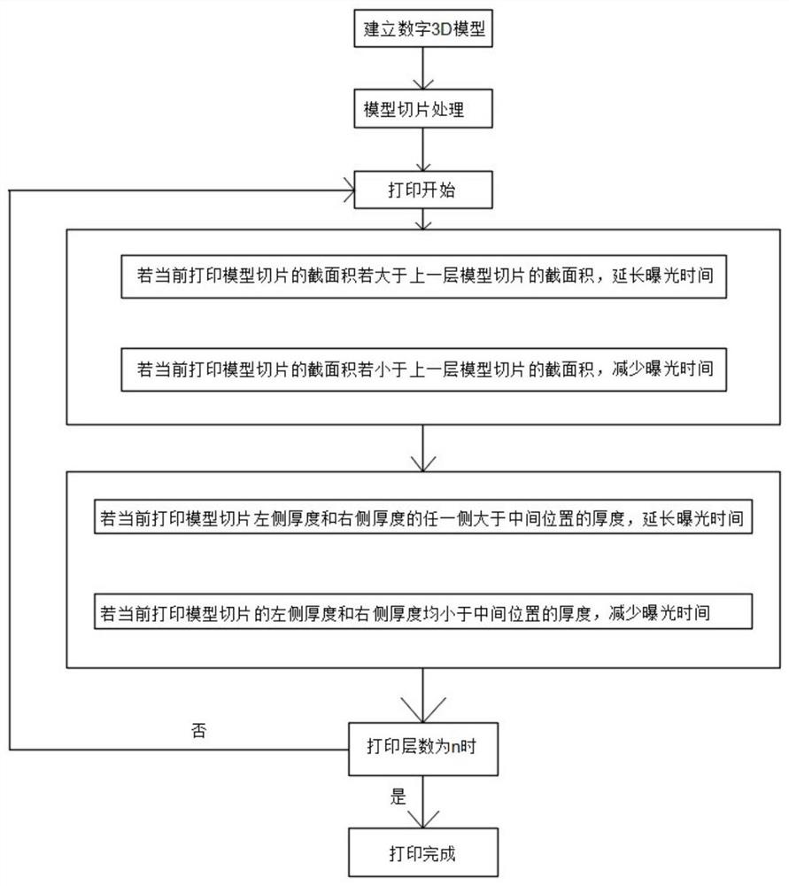
[0030] see figure 1 and image 3 , the present invention provides a technical solution: a printing method of a DLP light curing printer, comprising the following steps:
[0031] Step 1: Create a digital 3D model of the item to be printed;
[0032] Step 2: slice the digital 3D model to obtain multi-layer model slices, and the number of model slices is n;
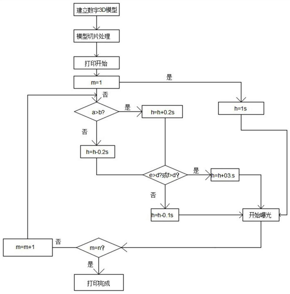
[0033] Step 3: From the bottom to the top of the digital 3D model, start printing from the first layer according to the model slice. The current number of printing layers is m, the exposure time is h, and h is 1s.
[0034] Step 4: Calculate the cross-sectional area of each layer of model slices, the cross-sectional area of the current printed model slice is a, the cross-sectional area of the previous layer of printed model slices is b, and calculate the thickness d of the middle position of each layer of model slices, and use The middle position of the model slice is scanned to both ends to obtain the thickness e on ...
Embodiment 2
[0047] see figure 1 and image 3 , the present invention provides a technical solution: a printing method of a DLP light curing printer, comprising the following steps:
[0048] Step 1: Create a digital 3D model of the item to be printed;
[0049] Step 2: slice the digital 3D model to obtain multi-layer model slices, and the number of model slices is n;
[0050] Step 3: From the bottom to the top of the digital 3D model, start printing from the first layer according to the model slice. The current number of printing layers is m, the exposure time is h, and h is 1s.
[0051] Step 4: Calculate the cross-sectional area of each layer of model slices, the cross-sectional area of the current printed model slice is a, the cross-sectional area of the previous layer of printed model slices is b, and calculate the thickness d of the middle position of each layer of model slices, and use The middle position of the model slice is scanned to both ends to obtain the thickness e on ...
PUM
 Abstract
Description
Claims
Application Information