
Method for forming cured coating film

A coating method and film coating technology, which is applied in the direction of photoplate making process coating equipment, etc., can solve the problems of inability to fill blind guide holes, flow of photosensitive resin composition, uneven thickness of cured coating film, etc., and achieve reliable filling Effects of embedding, shortening exposure time, and uniform thickness

Pending Publication Date: 2017-12-19
TAMURA KK
View PDF6 Cites 0 Cited by
  • Summary
  • Abstract
  • Description
  • Claims
  • Application Information

AI Technical Summary

Problems solved by technology

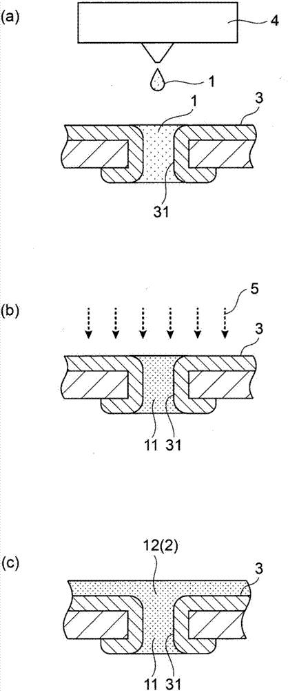
In this case, if the screen printing method is used, the blind via hole cannot be fully filled, and there is a problem that the photosensitive resin composition coated on the peripheral portion of the blind via hole will flow away.
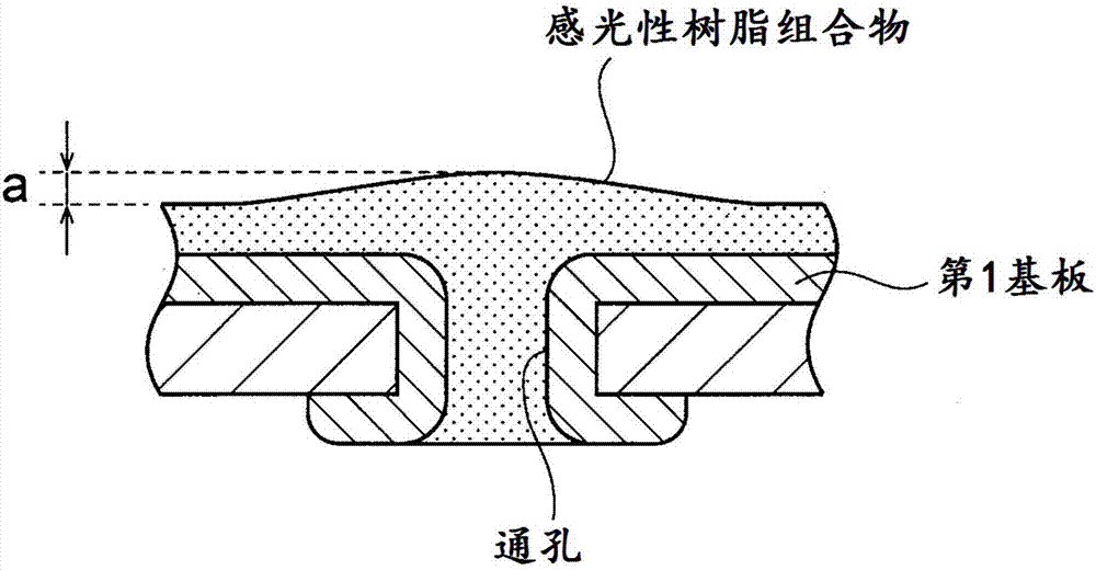
[0004] In addition, if a blind via hole is provided in a printed circuit board, since the blind via hole is not sufficiently filled with the photosensitive resin composition, the coated photosensitive resin composition flows away at its peripheral edge, so there are holes formed in the blind via hole. The problem that the thickness of the cured coating film on the printed circuit board becomes uneven

Method used


Image

  • Method for forming cured coating film
  • Method for forming cured coating film
  • Method for forming cured coating film

Examples


Embodiment 1~4、 comparative example 1~3

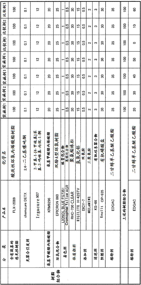
[0081] The components shown in the following Table 1 were blended in the compounding proportions shown in the following Table 1, mixed and dispersed at room temperature using a three-roll mill to prepare a resin composition, and a predetermined amount was added to the resin composition. diluent, and prepared the photosensitive resin composition used in Examples 1-4 and Comparative Examples 1-3. Then, the prepared photosensitive resin composition was apply|coated as follows, and the test piece was produced.

[0082] 【Table 1】

[0083]

[0084] Test piece production process

[0085] Substrate: set with inner diameter 1st substrate with a 70μm deep through-hole, provided with an inner diameter 2nd substrate with 70μm deep blind vias

[0086] Surface treatment: acid treatment (5 mass % sulfuric acid aqueous solution)

[0087] After the surface treatment, the photosensitive resins of Examples 1 to 4 and Comparative Examples 2 to 3 were dotted one by one using a jet dispen...

Embodiment 5~11、 comparative example 4

[0117] Next, as the UV irradiation machine used in the first curing process, instead of the above-mentioned UV irradiation machine using a metal halide lamp as a light source, an exposure device (manufactured by USHIO INC., model UX-2123SM) using an ultra-high pressure mercury lamp as a light source was used. ), so that the exposure amount of the first curing treatment becomes 10-100mJ / cm 2 Other than that, it carried out similarly to Example 3. That is, in Examples 5-11, the cured coating film was formed using the photosensitive resin composition of Example 3. The wavelengths of the ultra-high pressure mercury lamps are 365 nm, 385 nm, and 405 nm. Using ultra-high pressure mercury lamp to 30mJ / cm 2 The exposure time of the exposure is less than 1 second.

[0118] In Examples 5 to 11, the wavelength and exposure amount of the ultra-high pressure mercury lamp, and the results of via hole filling performance, blind via hole filling property, and coating film uniformity as the...


PUM

PropertyMeasurementUnit
Viscosityaaaaaaaaaa
Viscosityaaaaaaaaaa
Viscosityaaaaaaaaaa

Abstract

An object of the present invention is to provide a method for forming a cured coating film by which a through hole or a blind via can be sufficiently filled even if a through hole and a blind via are provided in the substrate and the thickness of the coating film can be made uniform. The method for forming the cured coating film includes the steps of: applying a first photosensitive resin composition having a viscosity of 120 to 3300 mPa s at 25 DEG C. to a substrate by an inkjet method; forming a first cured coating film from the applied first photosensitive resin composition by a first curing treatment; applying the second photosensitive resin composition to the first cured coating film; and forming a second cured coating film from the applied second photosensitive resin composition by a second curing treatment.

Description

technical field [0001] The present invention relates to a method for forming a cured coating film in which a photosensitive resin composition is discharged onto a substrate by an inkjet method to form a coating film. Background technique [0002] So far, when forming an insulating coating with a desired circuit pattern on a substrate such as a printed circuit board, the photosensitive resin composition is applied by a screen printing method, pre-dried, and the coating film of the photosensitive resin composition is A negative-type film having a pattern that makes light transmittance other than the pads of the circuit pattern is attached to it, and active energy rays are irradiated from above, and the non-exposed area corresponding to the pads is removed with a dilute alkaline aqueous solution to develop the coating film. And post-cure (patent document 1). [0003] However, sometimes blind vias are provided on printed circuit boards. In this case, if the screen printing met...

Claims


Application Information

Patent Timeline
IPC IPC(8): G03F7/16
CPCG03F7/16
Inventor 上杉尚之斋藤隆英木村健人冈本吉生
Owner TAMURA KK
Learn More