Gas-liquid separation device and consumption reduction method for gas-liquid separation device

A gas-liquid separation device and separator technology, which is applied in separation methods, chemical instruments and methods, and general layout of liquid degassing, etc., can solve the problems of low separation efficiency and high energy consumption of oil and gas separators

Active Publication Date: 2021-03-05
PETROCHINA CO LTD
View PDF9 Cites 0 Cited by
  • Summary
  • Abstract
  • Description
  • Claims
  • Application Information

AI Technical Summary

Problems solved by technology

[0005] The invention provides a gas-liquid separation device and a method for reducing consumption of the gas-liquid separation device, which solves the problem that the existing oil-gas separator is difficult to perform separation operations with optimal operating parameters, resulting in low separation efficiency of the oil-gas separator and energy efficiency. costly technical issues

Method used


Image

  • Gas-liquid separation device and consumption reduction method for gas-liquid separation device
  • Gas-liquid separation device and consumption reduction method for gas-liquid separation device
  • Gas-liquid separation device and consumption reduction method for gas-liquid separation device

Examples


Embodiment 1

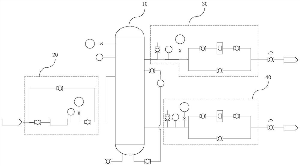
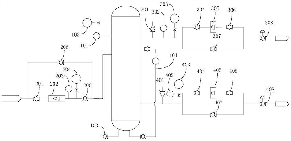
[0048] This embodiment provides a gas-liquid separation device, such as figure 1As shown, it is used to degas crude oil and physically separate the gas and liquid contained in the crude oil, including: a separator body 10, an inlet detection unit 20, a gas phase detection unit 30 and a liquid phase detection unit 40, wherein the separation The device body 10 is provided with an inlet pipeline, a gas phase outlet pipeline and a liquid phase outlet pipeline. The inlet pipeline is the inlet pipe of the separator body 10, and the inlet pipeline is mainly used to directly transport crude oil into the separator body 10. The gas phase outlet pipeline and the liquid phase outlet pipeline are the two outlet pipelines of the separator body 10. After the crude oil is separated in the separator body 10, it will form liquid and gas, and the gas will flow from the separator body 10 through the gas phase outlet pipeline. The liquid will flow out from the separator body 10 through the liquid ...

Embodiment 2

[0064] This embodiment provides a consumption reduction method for gas-liquid separation. The consumption reduction method is applied to the gas-liquid separation device provided in Embodiment 1. This consumption reduction method can adjust and optimize the operating parameters of the gas-liquid separation device to ensure separation efficiency. balance energy consumption.

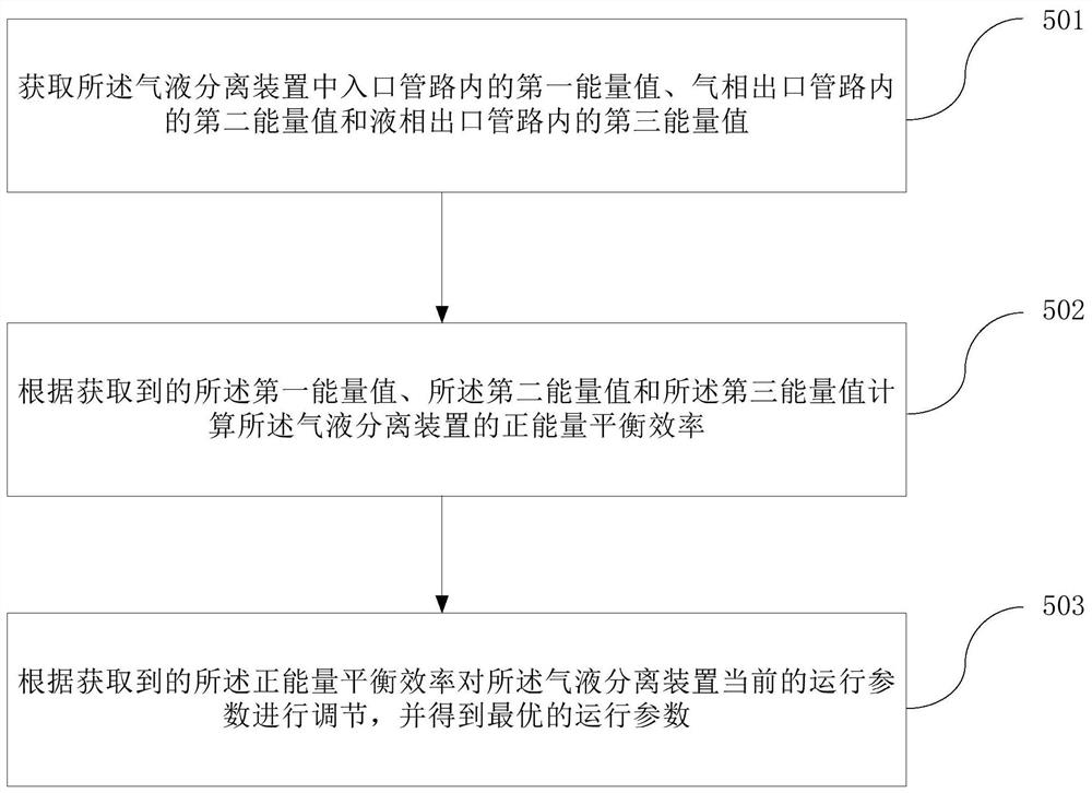
[0065] A method for reducing consumption of gas-liquid separation, such as image 3 shown, including the following steps:

[0066] Step 501. Obtain the first energy value in the inlet pipeline, the second energy value in the gas phase outlet pipeline and the third energy value in the liquid phase outlet pipeline in the gas-liquid separation device.

[0067] After the crude oil is exploited, it is directly passed into the gas-liquid separation device for gas-liquid separation. The separated gas material is transported to the gas phase outlet pipe, and the separated liquid material is transported to the liq...


PUM


Abstract

The invention provides a gas-liquid separation device and a consumption reduction method for the gas-liquid separation device. The gas-liquid separation device is used for degassing treatment of crudeoil, and the gas-liquid separation device comprises a separator body, an inlet detection unit, a gas phase detection unit and a liquid phase detection unit; and the inlet detection unit, the gas phase detection unit and the liquid phase detection unit are respectively used for detecting state parameters of liquid or gas in an inlet pipeline, a gas phase outlet pipeline and a liquid phase outlet pipeline so as to optimize operation parameters in the separator body. The gas-liquid separation device and the consumption reduction method for the gas-liquid separation device solves the technical problems of low separation efficiency and high energy consumption of an oil-gas separator due to the fact that the existing oil-gas separator is difficult to perform separation operation according to optimal operating parameters.

Description

technical field [0001] The invention relates to the technical field of petroleum equipment, in particular to a gas-liquid separation device and a consumption reduction method for the gas-liquid separation device. Background technique [0002] Generally, the unprocessed oil extracted directly from the oil field is called crude oil. Crude oil is a dark brown viscous oily liquid with green fluorescence and a special smell. Crude oil contains a lot of impurities, including oil , a mixture of gas and water, in order to facilitate the storage and transportation of crude oil, it is necessary to separate the crude oil into gas and liquid, and separate the crude oil according to gas and liquid. [0003] At present, crude oil generally uses an oil-gas separator for oil-gas separation. The oil-gas separator is placed between the submersible centrifugal pump and the protector to separate the free gas in the crude oil from the liquid. The liquid is sent to the submersible centrifugal pum...

Claims


Application Information

Patent Timeline
Patent Type & Authority Applications(China)
IPC IPC(8): E21B43/34E21B47/00B01D19/00C10G31/00
CPCE21B43/34E21B47/00B01D19/0068B01D19/00C10G31/00C10G2300/1033
Inventor 赵卫东牛明勇刘文东邓雄任军平隋志成王相飞何中凯张景山马文宏李思周东生
Owner PETROCHINA CO LTD
Why Eureka
Try Eureka