Water distributor and water distribution system for fuel cell

A water divider and sub-component technology, applied in chemical instruments and methods, separation methods, and dispersed particle separation, etc., can solve unfavorable water divider layout integration applicability, system volume power density, large flow resistance, and reduce structural costs And other issues

Pending Publication Date: 2022-04-29
SHANGHAI HYDROGEN PROPULSION TECH CO LTD
View PDF6 Cites 0 Cited by
  • Summary
  • Abstract
  • Description
  • Claims
  • Application Information

AI Technical Summary

Problems solved by technology

[0005] For the first type of water separator device, considering the water separation efficiency, enough space is needed for the settlement of the gas-liquid mixture, which is not conducive to improving the layout integration applicability of the water separation device and the system volume power density; for the second type of water separation device, the flow resistance is too large, the performance requirements are high, and the structure cost is reduced if it is not used

Method used


Image

  • Water distributor and water distribution system for fuel cell
  • Water distributor and water distribution system for fuel cell
  • Water distributor and water distribution system for fuel cell

Examples


Embodiment Construction

[0033] In order to enable those skilled in the art to better understand the technical solutions of the present invention, the present invention will be further described in detail below in conjunction with the accompanying drawings and specific embodiments.

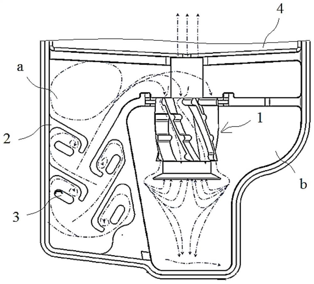
[0034] In this article, attached figure 2 The arrows in are the flow direction of the mixed fluid.

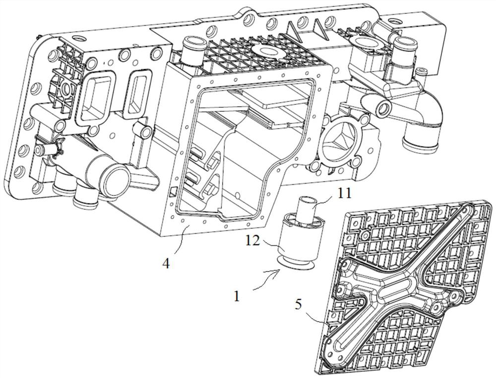
[0035] Please refer to Figure 1-Figure 2 , figure 1 It is a split view of a specific embodiment of the water distributor provided by the present invention; figure 2 for figure 1 Schematic diagram of the interior of the separation chamber in the water separator.

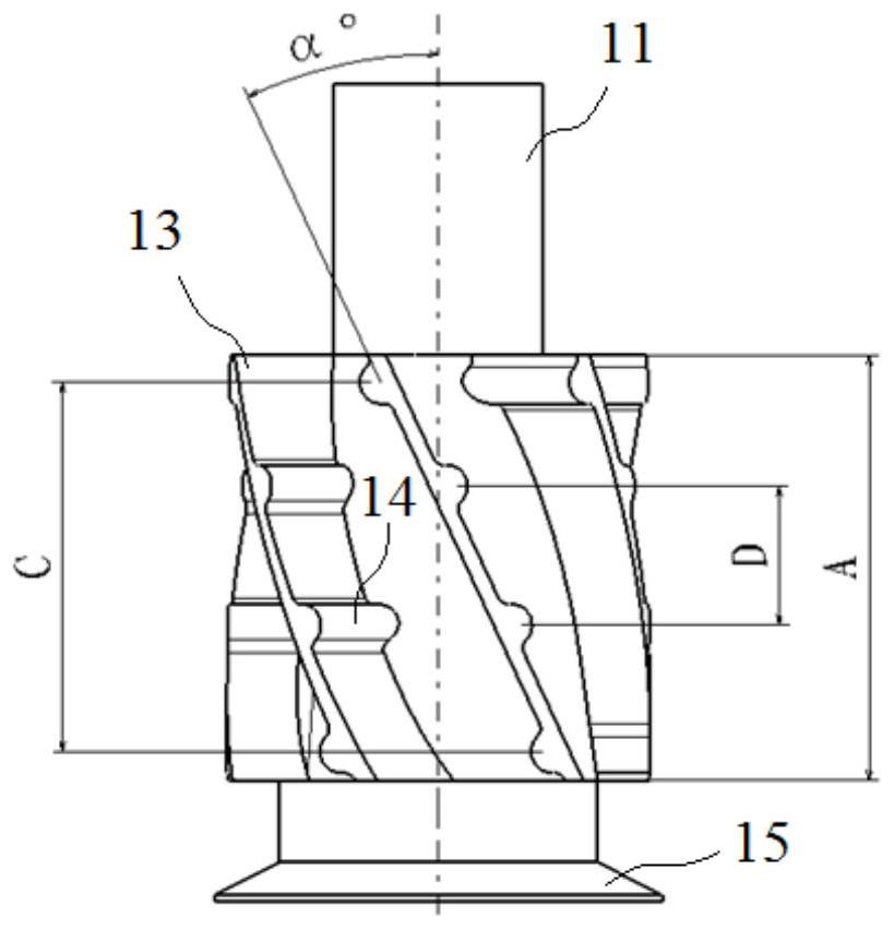
[0036] The present invention provides a water separator, which includes a separation chamber, the inside of which is divided into a baffle area a and a swirl area b, and also includes a baffle member and a swirl member 1, and the baffle member is arranged in the baffle area a , forming a baffle channel, the baffle area a and the swirl area b are only commu...


PUM


Abstract

The invention discloses a water segregator which comprises a separation cavity, and a baffling component is arranged in the separation cavity to form a baffling channel. A cyclone separation component (1) is further arranged in the separation cavity, and mixed fluid entering the separation cavity is subjected to gas-liquid separation through the baffling component and the cyclone separation component (1). The invention also provides a water distribution system for the fuel cell. The water separator is high in gas-liquid separation efficiency, simple in structure, small in size and convenient to manufacture, machine and install.

Description

technical field [0001] The invention relates to the technical field of fuel cells, in particular to a water separator and a water separation system for fuel cells. Background technique [0002] A fuel cell is a device that converts the chemical energy of hydrogen into electrical energy, and its product is water. Therefore, it has the advantages of zero emission, no pollution, low noise, high conversion efficiency, and can operate in a low temperature environment. It is a mobile power supply, base station power supply, etc. and stationary power sources of choice. [0003] During the operation of the anode system of the fuel cell, high-humidity gas will circulate in the anode pipeline. The high-humidity gas will produce liquid water due to saturated precipitation and condensation, so the fuel cell system will design a water separator in the anode pipeline. , to separate the water vapor from the exhaust gas of the fuel cell stack, and the unreacted gas enters the gas recycling...

Claims


Application Information

Patent Timeline
Patent Type & Authority Applications(China)
IPC IPC(8): B01D45/08B01D45/14
CPCB01D45/08B01D45/14
Inventor 李秋红杨威王鸿鹄蔡俊王克勇侯中军薛进营
Owner SHANGHAI HYDROGEN PROPULSION TECH CO LTD
Why Eureka
Try Eureka