Gas-liquid separation device for boat

A gas-liquid separation device and marine technology, applied in the field of marine power systems, can solve the problems of difficulty in adapting to the actual operation of marine power systems, complex changes in marine engine operating conditions, and increased installation difficulty due to large equipment volumes, so as to improve acoustic stealth. capacity, improve the efficiency of gas-liquid separation, and have the effect of large operating flexibility

Pending Publication Date: 2018-09-28
SHANGHAI MICROPOWERS
View PDF12 Cites 0 Cited by
  • Summary
  • Abstract
  • Description
  • Claims
  • Application Information

AI Technical Summary

Problems solved by technology

However, due to the limited space on the ship, the excessive volume of the equipment increases the difficulty of installation; and the change of the working conditions of the marine engine is more complicated, and the flow rate and mass ratio of the gas-liquid two-phase flow will change during the working process. The best gas-liquid separation effect can only be achieved at the rated operating point
Therefore, the traditional settling device is difficult to adapt to the actual operation of the marine power system, and the separation efficiency is low
In addition, when the pressure fluctuation of the exhaust system is large, the orifice plate structure in the traditional subsidence device also has the problem of excessive flow noise, and in severe cases, a continuous sharp high-frequency noise will be emitted

Method used


Image

  • Gas-liquid separation device for boat

Examples


Embodiment 1

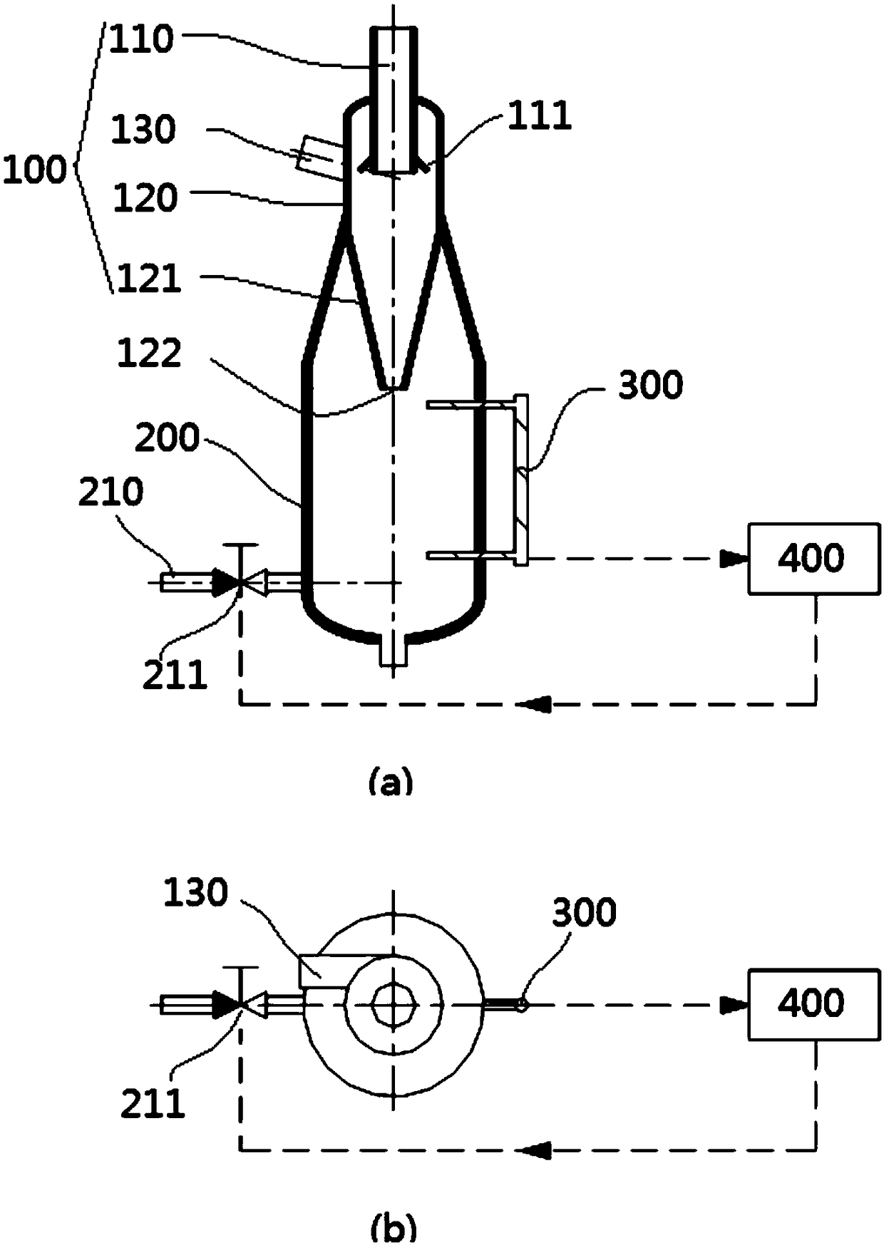
[0034] Such as figure 1 As shown, this embodiment discloses a marine gas-liquid separation device, including a gas-liquid cyclone unit 100 , a liquid storage unit 200 , a liquid level sensor 300 and a control unit 400 . (a) is the front view, (b) is the top view.

[0035] Wherein, the gas-liquid cyclone unit 100 includes an overflow pipe 110, an inlet pipe 130, and a main body, wherein the main body includes a cylindrical section 120 and a conical section 121 from top to bottom; the inlet pipe 130 communicates with the cylindrical section 120 to form a gas-liquid mixing inlet , the other end of the inlet pipe 130 communicates with the exhaust system of the marine engine, that is, the combustion product of the marine engine enters the marine gas-liquid separation device through the exhaust system, and the main component of the combustion product is CO 2 and H 2 A gas-liquid two-phase mixture of O. The upper end of the cylindrical section 120 is provided with an opening to pa...

Embodiment 2

[0040] Such as figure 1 As shown, on the basis of Embodiment 1, the upper end of the liquid storage unit 200 includes an opening to accommodate all or part of the conical section 121 inside, and the liquid storage unit 200 is integrally formed with the gas-liquid cyclone unit 100 or fixed through the opening. connect. That is, the conical section 121 is placed inside the liquid storage unit 200 through the opening, and the size of the entire device is reduced, which can be applied to a more compact installation space.

[0041] Exemplarily, a gas-liquid mixing inlet is provided on the side wall of the cylindrical section 120 , and the inlet pipe 130 is arranged tangentially to the cylindrical section 120 and is arranged obliquely downward toward the cylindrical section 120 .

[0042] The lower end of the overflow pipe 110 includes a skirt structure 111, and the height of the skirt structure 111 is approximately the same as or lower than that of the gas-liquid mixing inlet.


PUM


Abstract

The invention discloses a gas-liquid separation device for a boat. The gas-liquid separation device comprises a gas liquid cyclone unit, a liquid storage unit and a control unit, wherein a gas phase outlet, a gas liquid mixed inlet and a first liquid phase outlet are formed in the gas liquid cyclone unit from top to bottom; the liquid storage unit is positioned under the gas liquid cyclone unit and is communicated with the first liquid phase outlet; the lower part of the liquid storage unit is provided with a second liquid phase outlet; a control valve is arranged on the second liquid phase outlet; a liquid level sensor is arranged on the liquid storage unit so as to sense the liquid level in the liquid storage unit; the control unit is in communication connection with the control valve and the liquid level sensor, and controls the opening and closing state and / or the opening degree of the control valve according to the liquid level data feedback of the liquid level sensor, so that theratio of the gas phase space to the liquid phase space in the gas-liquid separation device for the boat can be maintained at the value around the set value. The device has the advantages that the installation is compact; the noise of an exhaust system can be reduced; the whole boat acoustic stealth capability is improved; the gas-liquid separation efficiency of the exhaust system can be improved;the downstream exhaust compressor can be protected to realize the long-time continuous and reliable operation.

Description

technical field [0001] The invention relates to a marine power system, in particular to a marine gas-liquid separation device. Background technique [0002] The combustion products of most marine engines are gas-phase two-phase flow in the exhaust system (or pipeline). In order to reduce the flow resistance of the exhaust system and protect the long-term continuous and reliable operation of the downstream compressor, a gas-liquid separation device is required to treat it. Traditionally, a sedimentation type gas-liquid separation device is generally used. Its structure is to install a filter plate with an orifice structure in the sedimentation chamber. In order to ensure the sedimentation effect of the droplets, this sedimentation chamber is designed for the rated operating point and has a large volume. However, due to the limited space on the ship, the excessive volume of the equipment increases the difficulty of installation; and the change of the working conditions of the ...

Claims


Application Information

Patent Timeline
Patent Type & Authority Applications(China)
IPC IPC(8): B01D45/16
CPCB01D45/16
Inventor 刘丰李启玉吴晓睿于健金渝博董克用林志民
Owner SHANGHAI MICROPOWERS
Why Eureka
Try Eureka