Anti-locking ratchet wheel self-locking mechanism

An anti-locking and ratchet technology, which is applied in mechanical equipment, load hanging components, transportation and packaging, etc., can solve problems affecting the production progress of the production line, difficulty in manual opening, and production stoppage of the production line, so as to reduce the probability of lock-up , reduce the contact area and prolong the service life

Inactive Publication Date: 2021-03-05
SHANGHAI BAOSIGHT SOFTWARE CO LTD +1
View PDF8 Cites 2 Cited by
  • Summary
  • Abstract
  • Description
  • Claims
  • Application Information

AI Technical Summary

Problems solved by technology

However, due to the matching angle and installation position of the ratchet and pawl, the original ratchet self-locking mechanism often makes manual opening very difficult, which affects the production progress of the entire production line, and in severe cases causes the production line to stop production, such as Figure 5 As shown, it is a schematic diagram of the ratchet self-locking structure. After the pawl 200 and the ratchet 100 contact and self-lock, the pointed surface of the pawl 200 is in close contact with the gear root 120 to self-lock, and the pawl 200 and the ratchet 100 are in a self-locking state. When the ratchet When 100 needs to rotate, the pawl 200 needs to be separated from the ratchet 100 by rotating and overcoming the self-locking resistance. The pawl tip 210 of the pawl 200 is deeply embedded in the gear root 120. Manual maintenance is urgently needed to separate the pawl 200 from the ratchet 100
In the process of frequently dealing with the abnormal self-locking of the ratchet 100, workers operate on the spreader for a long time, which poses a great safety hazard

Method used


Image

  • Anti-locking ratchet wheel self-locking mechanism
  • Anti-locking ratchet wheel self-locking mechanism
  • Anti-locking ratchet wheel self-locking mechanism

Examples


Embodiment Construction

[0038] The present invention will be described in detail below in conjunction with specific embodiments. The following examples will help those skilled in the art to further understand the present invention, but do not limit the present invention in any form. It should be noted that those skilled in the art can make several changes and improvements without departing from the concept of the present invention. These all belong to the protection scope of the present invention.

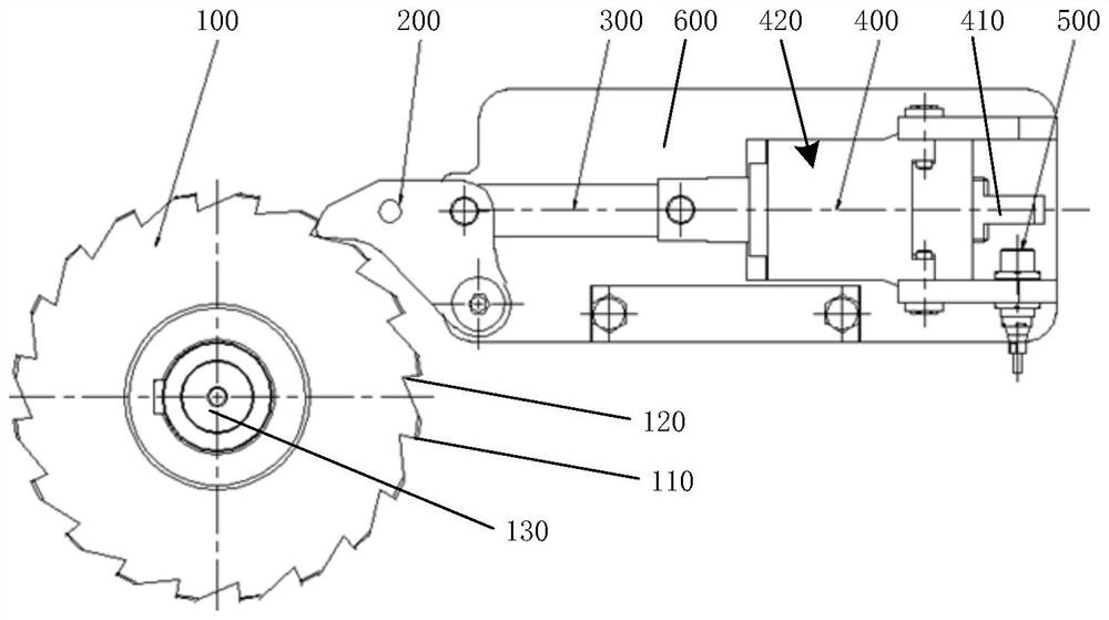
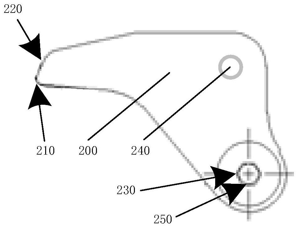
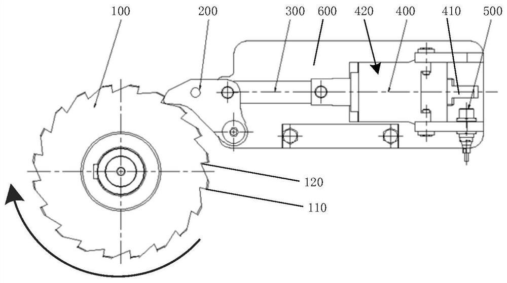
[0039] According to an anti-locking ratchet self-locking mechanism provided by the present invention, such as figure 1 As shown, it includes a ratchet 100, and also includes a pawl 200, a connecting rod 300, a traction electromagnet 400, and a state detection switch 500; One end of the connecting rod 300 is connected to the ratchet 200, and the other end is connected to the traction electromagnet 400. The state detection switch (500) can detect that the ratchet (200) is separated or locked from the rat...


PUM


Abstract

The invention provides an anti-locking ratchet wheel self-locking mechanism which comprises a ratchet wheel (100), a pawl (200), a connecting rod (300), a traction electromagnet (400) and a state detection switch (500). The traction electromagnet (400) can drive the pawl (200) to move towards two sides and realize separation and locking of the pawl (200) and the ratchet wheel (100), the connectingrod (300) is made of non-magnetic metal materials, a pawl round head (210) is arranged in an arc shape, a controller module (420) is installed in the traction electromagnet (400), and the traction electromagnet (400) adopts direct current and other measures, so that the pawl (200) and the ratchet wheel (100) are effectively prevented from being locked, operation efficiency is improved, productioncost is reduced, maintenance cost is reduced, and unsafe factors caused by maintenance are reduced.

Description

technical field [0001] The invention relates to the technical field of automatic control, in particular to an anti-locking ratchet self-locking mechanism. Background technique [0002] Today, when industrial control is highly automated, there have been cases where unmanned control is used for the hoisting of steel coils. When unmanned cranes are used for automatic hoisting, the positioning accuracy of automated cranes is much higher than that of manual positioning. At the same time, in order to improve the safety factor, many auxiliary detection switches and self-locking mechanisms need to be added to the spreader, which can effectively prevent the steel coil spreader from opening the clamp arm under abnormal conditions due to special reasons, causing accidents caused by the fall of the steel coil. During use, sometimes the ratchet self-locking mechanism is locked. In this state, the self-locking mechanism needs to be manually opened quickly for the next step. However, due ...

Claims


Application Information

Patent Timeline
Patent Type & Authority Applications(China)
IPC IPC(8): F16B1/04B66C1/10
CPCF16B1/04B66C1/10F16B2200/83
Inventor 张仲桢张玉建陈欣林魁圣刘朋
Owner SHANGHAI BAOSIGHT SOFTWARE CO LTD
Why Eureka
Try Eureka