
Optical cable rapid butt joint device

A docking device and fast technology, applied in the directions of light guides, optics, optical components, etc., can solve the problems of high scrap rate, low optical fiber splicing efficiency, and failure to reach the splicing process, saving time, facilitating optical cable splicing, and aligning speed. quick effect

Inactive Publication Date: 2021-03-05
西安万木春信息技术有限公司
View PDF0 Cites 0 Cited by
  • Summary
  • Abstract
  • Description
  • Claims
  • Application Information

AI Technical Summary

Problems solved by technology

[0002] With a large number of optical cables put into use, it is often necessary to splice the optical cables. At present, the splicing is mostly done manually, requiring multiple operators to operate. However, due to the technical requirements for the splicing of optical cables, manual splicing often occurs. The center line of the two spliced ​​optical cables is not in place. In a straight line, the requirements of the splicing process cannot be met, the efficiency of optical fiber splicing is low, and the scrap rate is high

Method used


Image

  • Optical cable rapid butt joint device
  • Optical cable rapid butt joint device

Examples


Embodiment Construction

[0015] The present invention will be described in detail below in conjunction with the accompanying drawings and specific embodiments.

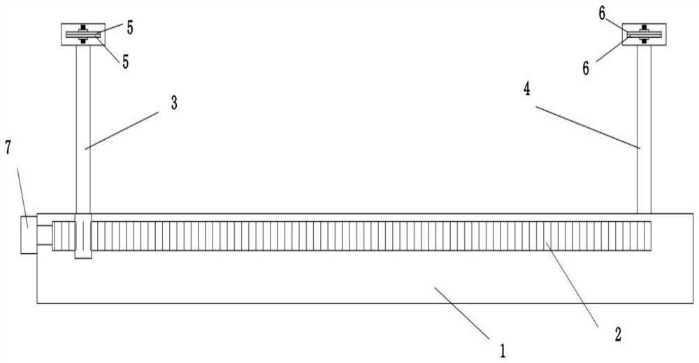
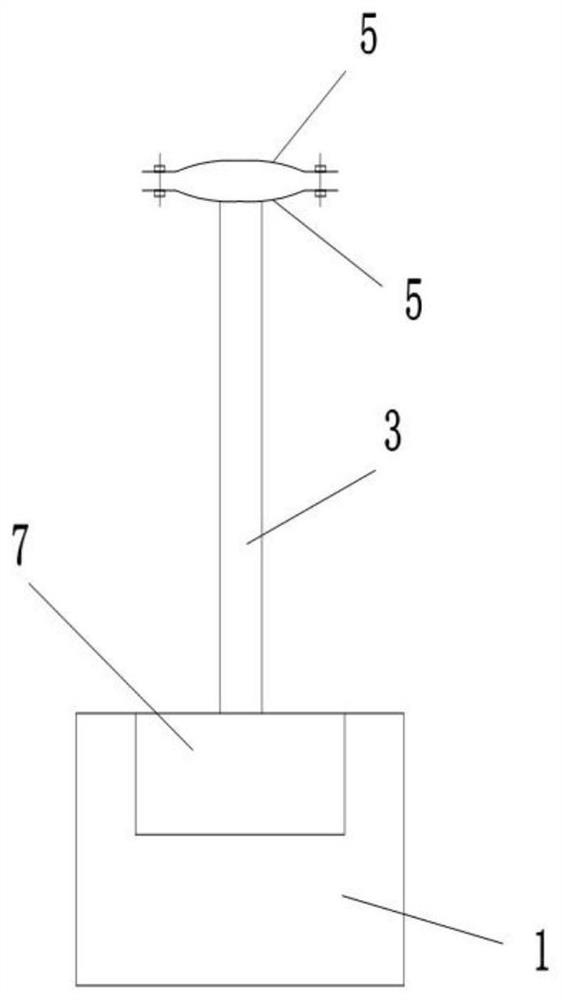
[0016] The present invention is an optical cable fast docking device, such as Figure 1-2 As shown, including the base 1, the base 1 is provided with a screw 2, the screw nut of the screw 2 is fixed with a support rod a3, the top of the support rod a3 is fixed with a clamping assembly a, and the base 1 is also fixed with a support rod b4 , the support rod b4 is close to the end of the screw of the lead screw 2, the top of the support rod b4 is fixed with the clamping component b, the screw 2 drives the clamping component a close to or away from the clamping component b, the clamping component a and the clamping component b are located at the same high.

[0017] The clamping assembly a includes two clamping plates a5 buckled up and down. The clamping plates a5 have radians. The radians of the two clamping plates a5 match the middle to form a ...


PUM


Abstract

The invention discloses an optical cable quick butt joint device, which comprises a base, wherein a lead screw is arranged in the base, a supporting rod a is fixed to the lead screw nut of the lead screw, a clamping assembly a is fixed to the top end of the supporting rod a, a supporting rod b is further fixed to the base, the supporting rod b is close to the tail end of the screw rod of the leadscrew, a clamping assembly b is fixed to the top end of the supporting rod b, the lead screw drives the clamping assembly a to be close to or away from the clamping assembly b, and the clamping assembly a and the clamping assembly b are located at the same height. According to the optical cable quick butt joint device, one cable is clamped and fixed, and after the other cable is clamped, the leadscrew is driven by the motor to get close to the fixed cable to achieve accurate alignment, so that the alignment speed is high, the efficiency is high, the continuous process requirement can be met,lots of manual alignment operation is omitted, and time is saved.

Description

technical field [0001] The invention belongs to the technical field of electric power auxiliary equipment, and relates to a fast connecting device for optical cables. Background technique [0002] With a large number of optical cables put into use, it is often necessary to splice the optical cables. At present, the splicing is mostly done manually, requiring multiple operators to operate. However, due to the technical requirements for the splicing of optical cables, manual splicing often occurs. The center line of the two spliced ​​optical cables is not in place. In a straight line, the requirements of the splicing process cannot be met, the efficiency of optical fiber splicing is low, and the scrap rate is high. Contents of the invention [0003] The purpose of the present invention is to provide a quick connection device for optical cables, which can clamp two continuous optical cables and realize quick alignment. [0004] The technical solution adopted in the present i...

Claims


Application Information

Patent Timeline
Patent Type & Authority Applications(China)
IPC IPC(8): G02B6/36
CPCG02B6/36G02B6/3616
Inventor 唐梦洁
Owner 西安万木春信息技术有限公司
Learn More