Head-up display equipment, imaging system and vehicle
A head-up display and equipment technology, applied in the computer field, can solve the problems of reducing the driver's experience of using AR-HUD and deviating from the real environment, so as to improve the user experience and eliminate the effect of horizontal parallax
- Summary
- Abstract
- Description
- Claims
- Application Information
AI Technical Summary
Problems solved by technology
Method used
Image
Examples
Embodiment 1
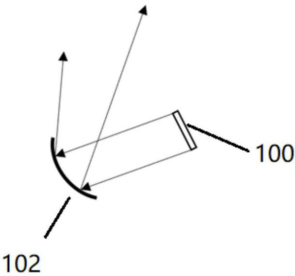
[0042] see Figure 1a A schematic structural diagram of a head-up display device is shown. This embodiment proposes a head-up display device, including: an image source 100 and a curved mirror 102 .
[0043]The image source 100 is set at a position close to the focal plane of the curved mirror 100 or at a position where the focal plane of the curved mirror 102 is located.
[0044] The image source 100 can emit light.
[0045] Further, the image source 100 can emit light to present an image.
[0046] The curved mirror 102 reflects the incident light out of the head-up display device, so that the light reflected out of the head-up display device can form a long-distance virtual image.
[0047] The curved mirror 102 may be, but not limited to: a spherical mirror, a hyperbolic mirror, a parabolic mirror, and a free-form mirror.
[0048] The distant virtual image is used to eliminate the horizontal parallax when the observer watches the image.
[0049] Here, the principle of the...
Embodiment 2
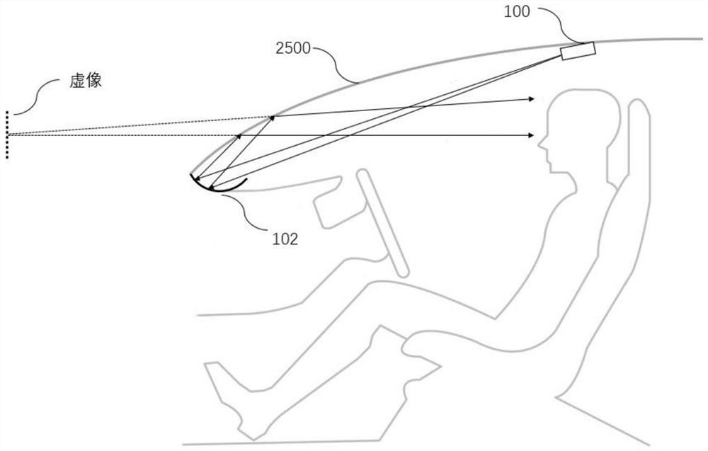
[0116] see image 3 Shown is a schematic structural diagram of a vehicle cockpit installed with a head-up display device. This embodiment proposes a head-up display device, including: an image source 100 .
[0117] The image source 100 is installed in a vehicle; at least one surface of the dashboard 4700 of the vehicle has a curved reflective structure 4702 .
[0118] The image source 100 is set in the vehicle near the focal plane of the curved reflective structure 4702 or at the position of the focal plane of the curved reflective structure 4702 .
[0119] The image source 100 can emit light.
[0120] Further, the image source 100 can emit light to present an image.
[0121] The curved surface reflection structure 4702 reflects the light emitted by the image source 100 to the vehicle windshield 2500 , so that the light reflected to the vehicle windshield 2500 can form a long-distance virtual image.
[0122] The distant virtual image is used to eliminate the horizontal para...
Embodiment 3
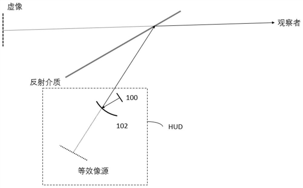
[0147] see Figure 4 with Figure 5 As shown in the structural diagrams of different vehicle cockpits, this embodiment proposes an imaging system, including: a vehicle windshield 2500 and the HUD 2502 described in Embodiment 1.
[0148] in, Figure 4 The HUD2502 shown in the Figure 5 The HUD2502 shown in is has a flat mirror.
[0149] The vehicle windshield 2500 reflects the light received from the head-up display device 2502 to the observer's eye box area, so that the observer can observe that the vehicle windshield is moving away from the head-up display device A distant virtual image of one side of 2502.
[0150] The vehicle windshield 2500 may be, but not limited to, transparent or non-transparent media with a certain inclination angle, such as a vehicle windshield, a plane mirror coated with an opaque reflective layer, or a transparent resin plate.
[0151] This embodiment also proposes a vehicle, which may include the above-mentioned imaging system.
[0152] To su...
PUM
 Abstract
Description
Claims
Application Information
 - R&D
- Intellectual Property
- Life Sciences
- Materials
- Tech Scout
- Unparalleled Data Quality
- Higher Quality Content
- 60% Fewer Hallucinations
Browse by: Latest US Patents, China's latest patents, Technical Efficacy Thesaurus, Application Domain, Technology Topic, Popular Technical Reports.
© 2025 PatSnap. All rights reserved.Legal|Privacy policy|Modern Slavery Act Transparency Statement|Sitemap|About US| Contact US: help@patsnap.com


