Imaging System For Digital Stereo Microscope

a digital stereo microscope and imaging system technology, applied in the field of digital stereo microscopes, can solve the problems of difficult operation of optical microscopes, inability to observe any image, and difficult to achieve synchronization in practice, so as to facilitate use, enhance versatility of microscopes, and eliminate horizontal parallax

Active Publication Date: 2014-08-28
GUANGZHOU JINGHUA PRECISION OPTICS CO LTD
View PDF6 Cites 9 Cited by
  • Summary
  • Abstract
  • Description
  • Claims
  • Application Information

AI Technical Summary

Benefits of technology

[0021]It is preferable that the output selection module read out, within a row cycle for controlling read out, the rows to be read out in the left memory unit and the right memory unit from at least a different start point or an end point to eliminate horizontal parallax between the left eye image data and the right eye image data.
[0022]It is preferable that horizontal parallax between the left eye image data and the right eye image data output by the respective camera unit is adjusted by the output selection module during read out by reading out the required rows from the left eye image data and the right eye image data and removing the data in the rows that are misaligned, so that the vertical misalignment between the optical axes of the left lens and the right lens can be corrected.
[0023]The invention is advantageous in that it is no longer necessary for the imaging system to observe the subject with the binocular eyepiece, i.e. the double eye lens. Moreover, in a standalone system, the stereo video or stereo picture can be synthesized in the synchronous synthesizer and therefore can be compressed and stored, and by the conversion of the stereoscopic display convertor the video or picture can be displayed in naked eye three-dimensional form via a stereo display. In addition, the imaging system can also be connected to a large scale display, and can be incorporated with 2D display functionalities, so as to enhance versatility of the microscope and thus facilitate use of the same.

Problems solved by technology

These optical microscopes can be difficult to operate and in extreme cases even cannot observe any image for an inexperience person.
It has been proved however, synchronization in this manner is very difficult to achieve in practice.
Moreover, the stereo vision is achieved by a convex lens which also demands high operation technique in practice and is not suitable for naked eyes stereo image display.

Method used


Image

  • Imaging System For Digital Stereo Microscope
  • Imaging System For Digital Stereo Microscope
  • Imaging System For Digital Stereo Microscope

Examples


Embodiment Construction

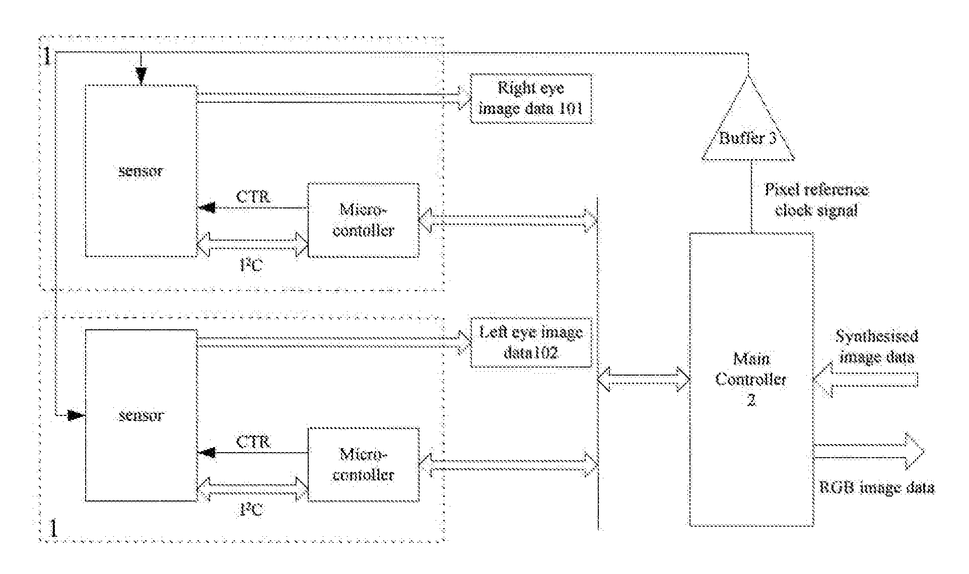
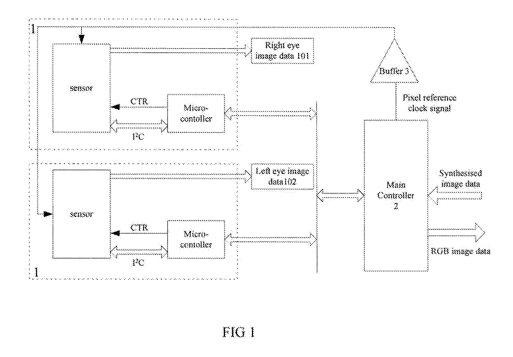
[0027]As shown in FIG. 1, an imaging system for a digital stereo microscope according to one embodiment of the invention is illustrated. The system comprises two camera units 1 for the left eye and the right eye of a human being, the two camera units have identical optical magnification and each camera unit 1 is constructed by a lens module, a sensor for capturing imaging and a microcontroller for configuring and controlling the sensor, that is, the imaging parameters, such as brightness and contrast, is adjusted by the microcontroller. Here, as illustrated in FIG. 1, the microcontroller can exchange data, i.e. mostly the imaging parameters, with the sensor via I2C bus, the microcontroller outputs control signal CTR to control the working status, such as start and reset, of the sensor. The two lens modules can be configured such that light passes the two lens modules will converge and focus at one point. The focusing point of lens modules normally lies within the plane of an object ...


PUM


Abstract

An imaging system for digital stereo microscope is disclosed, wherein the system comprising two camera units with each camera unit comprises a lens and the two lenses of the two camera units are focused below the respective lens and optical axes of both lenses are arranged to focus at a same point; a main controller configured to provide both sensors with a common trigger signal for outputting image data and a common pixel reference clock signal for each sensor to generate its own pixel clock signal; a synchronous synthesizer for generating synthesized image data with left eye image data located on the left side and the right eye image data located on right side by synchronizing and synthesizing the left eye data and the right eye image data output by the respective sensor; the synthesized image data is compresses and encoded in the main controller to generate RGB image data corresponding to parallel image data; a stereoscopic display convertor for receiving the RGB image data and converting the received RGB image data into a format that is recognizable by a stereo display.

Description

TECHNICAL FIELD[0001]The present invention relates to digital stereo microscopes, and in particular relates to imaging system of a digital stereo microscope which can be widely used in areas such as manufacturing, researching, medication, and education.BACKGROUND ART[0002]All of today's stereo microscopes are optical microscopes which observe object through binocular eyepiece. These optical microscopes can be difficult to operate and in extreme cases even cannot observe any image for an inexperience person. Chinese Patent No CN201740916U published on Feb. 9, 2011 discloses a stereo microscope which consists of a double eye observing device, a parallel light stereo zoom lens body having focusing and supporting rack, a stereo digital body, and a digital display device. In this microscope, a reflective component is inserted into a branch path of the stereo microscope, through which images are formed on the image sensor of the stereo digital body and are then provided to the digital dis...

Claims


Application Information

Patent Timeline
Patent Type & Authority Applications(United States)
IPC IPC(8): G02B21/36H04N13/02H04N13/00G03B35/08
CPCG02B21/367H04N13/0029H04N13/0239H04N13/0037G02B21/22H04N13/139H04N13/239H04N13/15
Inventor XIA, DENGHAI
Owner GUANGZHOU JINGHUA PRECISION OPTICS CO LTD
Why Eureka
Try Eureka