Check patentability & draft patents in minutes with Patsnap Eureka AI!

Wafer concentric normalizing device

A wafer and regular technology, which is applied in the field of wafer concentric regularization devices, can solve the problems of inconvenient wafer handling, inconvenience in taking and placing, influence of centering accuracy, inaccurate positioning, etc., so as to improve production efficiency and processing quality. , The effect of improving working conditions and accurate positioning accuracy

Inactive Publication Date: 2021-03-05
SUZHOU TIANHONG LASER
View PDF0 Cites 0 Cited by
  • Summary
  • Abstract
  • Description
  • Claims
  • Application Information

AI Technical Summary

Problems solved by technology

The size of wafers on the market is 2 inches to 12 inches. The traditional clamping and centering method is to place the workpiece on the concentric circle base, and position the processed step circle on the base with the outer ring of the wafer. The positioning method is fixed centering, that is, each wafer is centered by a concentric step circle, so that the centering accuracy is affected by the concentricity of each step circle of the tooling; and because of the need to pick and place, the outer ring of the wafer and the The inner diameter gap of the stepped circle should not be too large or too small. If the gap is too large, it will affect the concentricity. If the gap is too small, it is inconvenient to pick and place wafers.
Due to the large number of outer diameter specifications, it is necessary to make multiple stepped circles, resulting in a thicker concentric circle base, and many sizes need to be precisely processed, which requires a large processing cost
Another way to tighten the positive and negative nuts by screw rotation, so that the V-shaped block clamps the wafer, but the screw connection has a large backlash, which is prone to inaccurate positioning

Method used


Image

  • Wafer concentric normalizing device
  • Wafer concentric normalizing device
  • Wafer concentric normalizing device

Examples


Embodiment

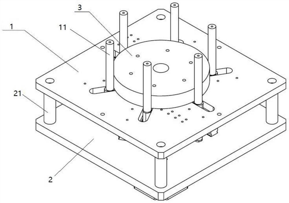
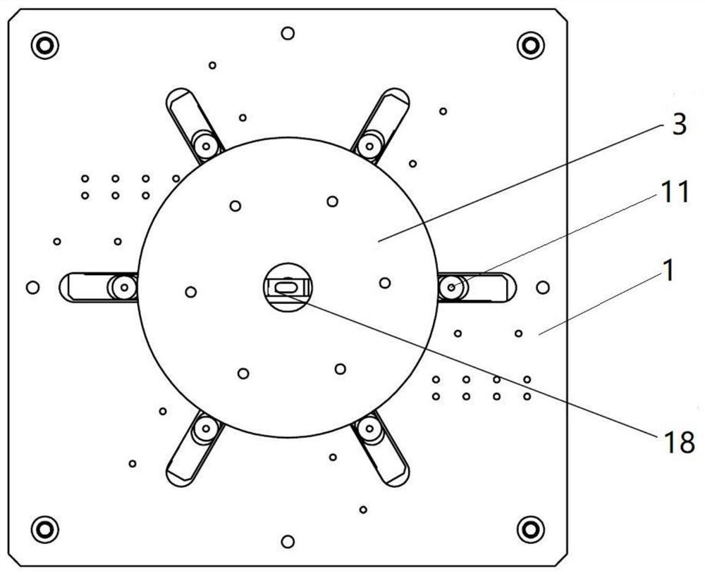
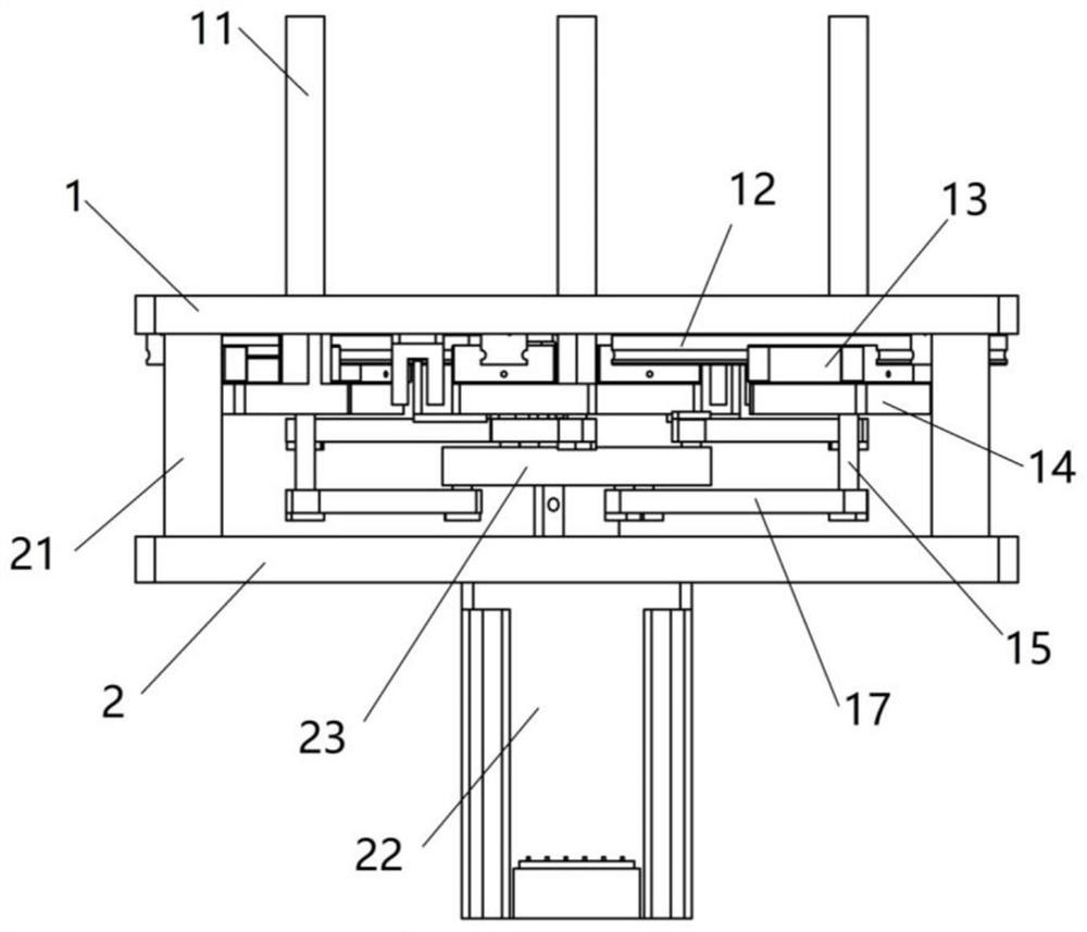
[0019] Such as figure 1 Only Figure 4 As shown, a wafer concentric regularization mechanism includes a mounting plate 1, a fixed plate 2 and a regular mechanism; the mounting plate 1 is mounted on the fixed plate 2 through a support shaft 21; One side is provided with a linear guide rail 12; the linear guide rail 12 is provided with a slider 13; the bottom of the fixed plate 2 is provided with a stepping motor 22; the center of the mounting plate 1 is provided with a circular hole, and the There is an inductive switch 18; the mounting plate 1 is also provided with a limit device that limits the regularization mechanism.

[0020] The regularizing mechanism includes a regularizing shaft 11, a chain bar 17 and a turntable 23; the bottom of the regularizing shaft 11 is connected with a slider connector 14; the slider connector 14 is fixedly connected to the slider 13; the chain bar 17 One end of it is connected with the slider connector 14 through the long positioning pin 15, a...


PUM


Abstract

The invention relates to the technical field of wafer processing, and discloses a wafer concentric normalizing device which comprises a mounting plate, a fixing plate and a normalizing mechanism. Themounting plate is mounted on the fixed plate through a supporting shaft; a linear guide rail is arranged on one surface, close to the fixed plate, of the mounting plate; a sliding block is arranged onthe linear guide rail; a stepping motor is arranged at the bottom of the fixing plate; a circular hole is formed in the center of the mounting plate, and an inductive switch is arranged in the circular hole; and a limiting device for limiting the regulating mechanism is further arranged on the mounting plate. According to the invention, the regular shafts for clamping the workpiece can move centripetally at the same time, and the moving distances are completely equal, so that the positioning precision is accurate, and the automatic clamping and centering of the workpiece are realized. The stretching structured blocks are used for clamping, and different lengths can be designed according to different workpieces. The device is driven by a stepping motor, manual work is replaced, the production efficiency and the machining quality are greatly improved, and the labor condition is improved.

Description

technical field [0001] The invention relates to a wafer processing device, in particular to a wafer concentric regularization device. Background technique [0002] With the improvement of the technical capabilities of the domestic machinery and equipment industry, equipment automation has become an inevitable trend in the development of enterprises, especially the technical transformation and upgrading of existing equipment to meet the requirements of equipment automation, reduce the time for tooling replacement, repeat the cost of tooling, and reduce the workload of operators. Labor intensity, improving work efficiency has become an urgent problem to be solved. The size of wafers on the market is 2 inches to 12 inches. The traditional clamping and centering method is to place the workpiece on the concentric circle base, and position the processed step circle on the base with the outer ring of the wafer. The positioning method is fixed centering, that is, each wafer is cent...

Claims


Application Information

Patent Timeline
Patent Type & Authority Applications(China)
IPC IPC(8): H01L21/67
CPCH01L21/67092
Inventor 朱赛勇
Owner SUZHOU TIANHONG LASER
Features
  • R&D
  • Intellectual Property
  • Life Sciences
  • Materials
  • Tech Scout
  • Unparalleled Data Quality
  • Higher Quality Content
  • 60% Fewer Hallucinations
Learn More