Connector device

A technology of connectors and equipment, which is applied in the direction of printed circuits connected with non-printed electrical components, printed circuits assembled with electrical components, etc., can solve the problems of high processing costs, low production efficiency, and high welding difficulty, and achieve production costs. Low cost, high production efficiency, simple and convenient processing

Pending Publication Date: 2021-03-05
ZTE CORP
View PDF0 Cites 0 Cited by
  • Summary
  • Abstract
  • Description
  • Claims
  • Application Information

AI Technical Summary

Problems solved by technology

[0004] The embodiment of the present application provides a connector device, which is used to solve the problems of high welding difficulty, difficult to guarantee the quality of welding, low production efficiency and high processing cost existing in the prior art.

Method used


Image

  • Connector device
  • Connector device

Examples


no. 1 example

[0028] An embodiment of the present application provides a connector device, which can be used in communication products, consumer electronics products and other electronic products that require signal transmission, for example, it can be used in optoelectronic integrated equipment in the power communication industry.

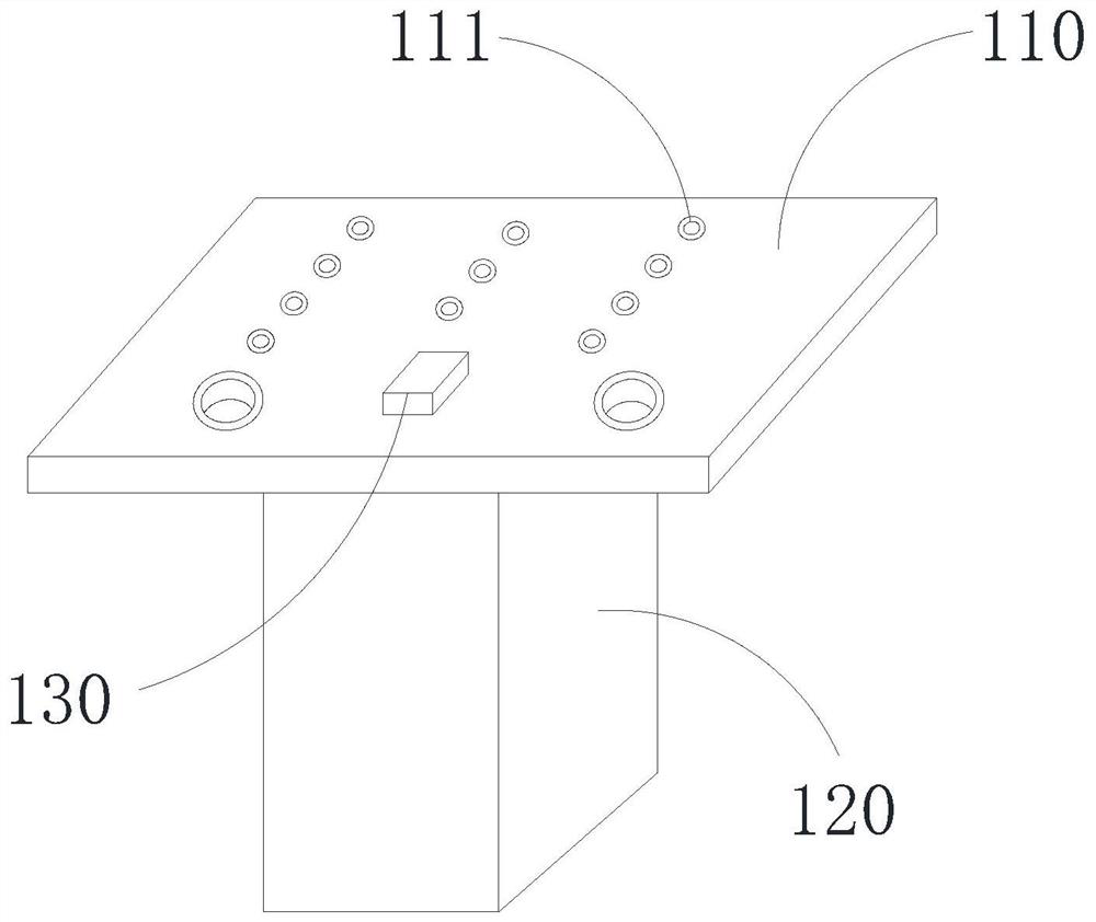
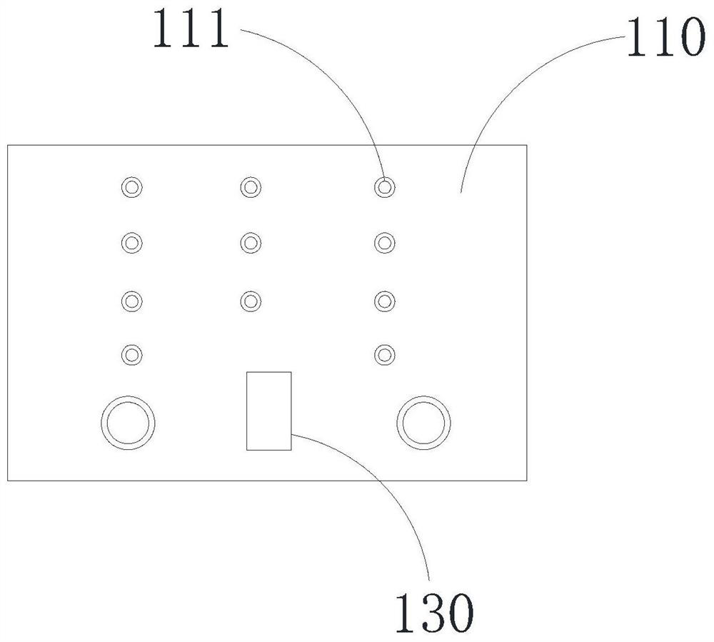
[0029] see figure 1 and figure 2 , the connector device includes a printed circuit board 110, a connector 120, and an indicator light 130, the printed circuit board 110 has a first surface and a second surface, the connector 120 is connected to the first surface of the printed circuit board 110, indicating The light 130 is connected to the second surface of the printed circuit board 110 and is electrically connected to the wires arranged on the printed circuit board 110 , and the wires arranged on the printed circuit board 110 are electrically connected to the connector 120 and the indicator light 130 .

[0030] In the embodiment of the present application, t...

no. 2 example

[0042] see figure 1 and figure 2 , the embodiment of the present application provides a connector device, the connector device includes a printed circuit board 110, a connector 120 and an indicator light 130, the printed circuit board 110 has a first surface and a second surface, and the connector 120 is connected to On the first surface of the printed circuit board 110, the indicator light 130 is connected to the second surface of the printed circuit board 110 and is electrically connected to the wires arranged on the printed circuit board 110, and the wires arranged on the printed circuit board 110 will The connector 120 is electrically connected with the indicator light 130 .

[0043] Wherein, the connector 120 is soldered to the first surface of the printed circuit board 110 by soldering iron, and the indicator light 130 is soldered to the second surface of the printed circuit board 110 by soldering iron.

[0044] To sum up, in the connector device provided by the embod...


PUM


Abstract

The invention discloses connector equipment, and relates to the field of connecting equipment. The connector device includes: a printed circuit board having a first surface and a second surface; a connector which is connected to the first surface; an indicating lamp which is connected to the second surface and is electrically connected with a wire arranged on the printed circuit board; wherein theconnector is electrically connected with the indicating lamp through a lead arranged on the printed circuit board. The connector equipment disclosed by the invention has the advantages of simple andconvenient processing, high production efficiency, low production cost and the like.

Description

technical field [0001] The present application relates to the field of connecting devices, in particular to a connector device. Background technique [0002] A large number of connectors are used in communication products and consumer electronics products, which improves the signal transmission of electronic products, simplifies the production process of electronic products, makes products easy to repair and upgrade, and improves design flexibility. [0003] In the production process of communication products and consumer electronic products, it is often necessary to set an indicator light to indicate the working status of a connector soldered on a printed circuit board (Printed Circuit Board, PCB). At present, the commonly used method is to set the indicator light inside the connector and solder it on the printed circuit board by wave soldering. Since the indicator light is arranged inside the connector, there are problems such as high difficulty in welding, difficult to g...

Claims


Application Information

Patent Timeline
IPC IPC(8): H05K1/18H05K3/34
CPCH05K1/18H05K3/34
Inventor 孟祥华何日吉
Owner ZTE CORP
Why Eureka
Try Eureka