Method for controlling the input voltage frequency of a dc-dc convertor
A technology for controlling frequency and current converters, used in converter types, conversion of DC power input to DC power output, control/regulation systems, etc., and can solve problems such as inability to provide solutions
- Summary
- Abstract
- Description
- Claims
- Application Information
AI Technical Summary
Problems solved by technology
Method used
Image

Examples
Embodiment Construction
[0046] Figure 1 to Figure 6 The same embodiment is referred to and will be annotated at the same time.
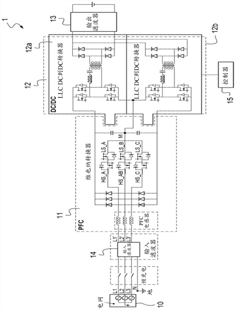
[0047] refer to figure 1, a charger 1 connected to a battery 13 of a three-phase grid 10 comprising a power factor correction stage 11 (also referred to as PFC stage 11) and DC current to DC current converters DC to DC 12a and 12b, each having an inverter device 212.
[0048] The three-phase grid 10 is mounted on an input filter 14 which delivers the filtered input current to the PFC stage 11 .
[0049] At the output of the PFC 11 the two DC voltage buses connected to the terminals of the output capacitors of the PFC stage 11 are respectively coupled to DC to DC converters 12a, 12b which are connected in parallel with the battery 13 at the output.
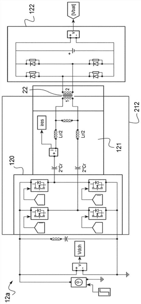
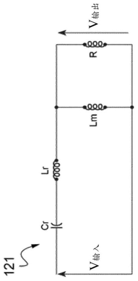
[0050] Each DC to DC 12a, 12b ( figure 2 Only one example is shown in ) including input MOSFET bridge 120, LLC circuit 121 (simplified circuit diagram of which is shown in image 3 shown), transformer 22 and output diode ...
PUM
 Abstract
Description
Claims
Application Information
PatSnap Eureka turns technology decisions into work you can execute. Powered by our Innovation Knowledge Graph, it runs expert workflows across engineering, life sciences, materials and intellectual property. Get your review-ready output in minutes.


