Separation system for continuous casting

A technology of continuous casting and slab casting, which is applied in the direction of furnace, furnace type, heat treatment equipment, etc. It can solve the problems of high requirements for equipment automation control, difficulty in meeting, unfavorable hooking up of slab under hooking machine, etc., so as to avoid impact effect

Active Publication Date: 2022-05-20
CONTINUOUS CASTING TECH ENG OF CHINA
View PDF13 Cites 2 Cited by
  • Summary
  • Abstract
  • Description
  • Claims
  • Application Information

AI Technical Summary

Problems solved by technology

[0003] The above-mentioned existing scheme has the following disadvantages: when the steel pusher pushes the cast slabs onto the 1# hot delivery roller table in turn, the cast slabs are in groups and close together one by one. The movement trajectory is arc-shaped, so this state is not conducive to hooking the billet with the lower hook of the hooking machine. At this time, the hooking machine needs to be lowered in advance. The steel machine runs in the opposite direction, away from the 1# hot delivery roller table, so as to reduce or eliminate the mutual impact between the hook steel machine and the casting slab when hooking the slab, and protect the equipment and the casting slab. In this case, the requirements for automatic control of the equipment are extremely high. high, not easy to satisfy

Method used


Image

  • Separation system for continuous casting
  • Separation system for continuous casting
  • Separation system for continuous casting

Examples


Embodiment Construction

[0033] The present invention will be further described below in conjunction with the accompanying drawings and embodiments.

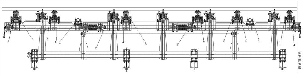
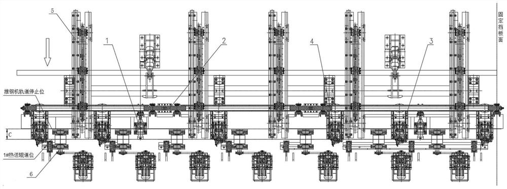
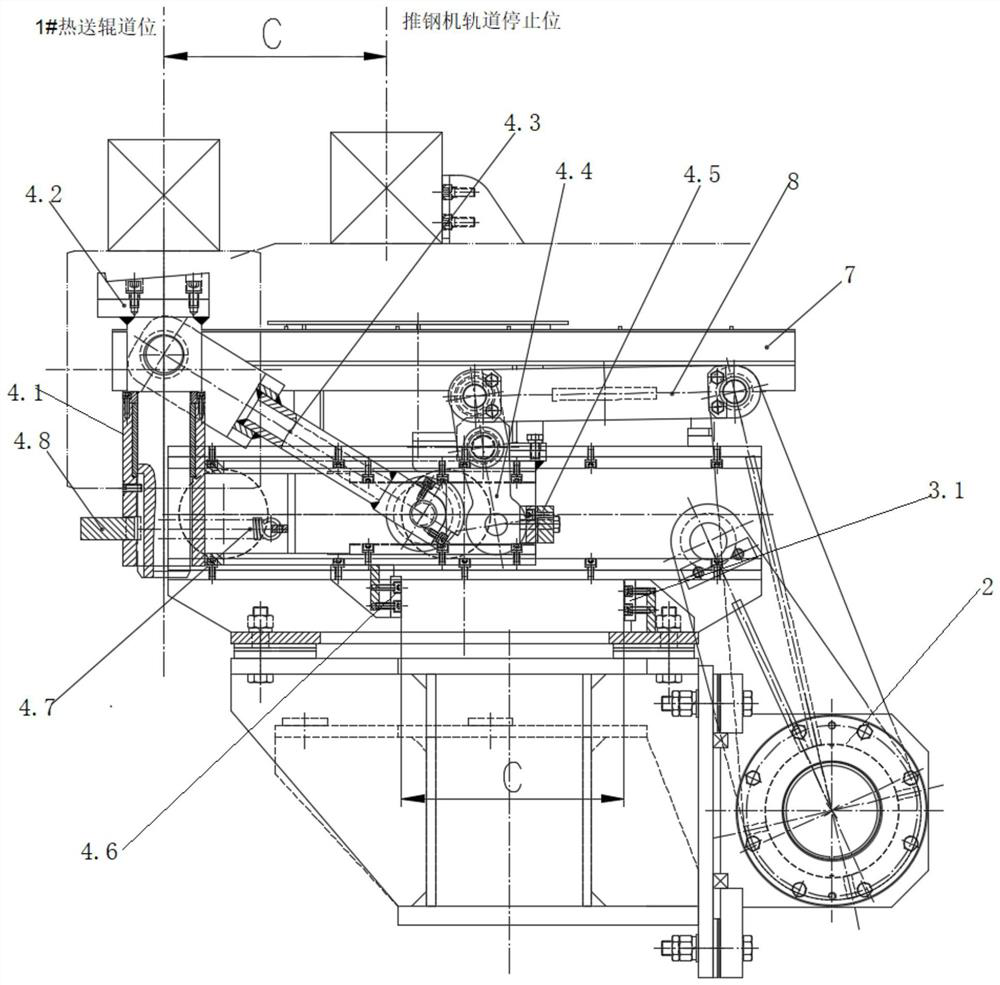
[0034] like Figure 1 to Figure 9 As shown, a steel splitting system for continuous casting includes a synchronous shaft 2, a hydraulic cylinder 1, a guide rail frame 3 and a billet trolley 4, the synchronous shaft 2 is parallel to the longitudinal direction of the billet, and the hydraulic cylinder 1 and guide rail frame 3 are perpendicular to the billet Longitudinal and along the longitudinal direction of the billet, it is distributed in the remaining space of the pusher rail beam 5, 1# hot-feeding roller table 6 and hook claws of the steel hooking machine. The supporting blank trolley 4 is fitted on the guide rail of the guide rail frame 3 through the wheels 4.13 without falling out. 3.5, the blank support trolley 4 is equipped with a lifting rod 4.2 for supporting the casting slab, all the hydraulic cylinders 1 drive all the blank support trolleys 4...


PUM


Abstract

The invention discloses a steel separating system for continuous casting, which comprises a synchronous shaft, a hydraulic cylinder, a guide rail frame and a billet supporting trolley, the synchronous shaft is parallel to the longitudinal direction of the billet, the hydraulic cylinder and the guide rail frame are perpendicular to the longitudinal direction of the billet and along the longitudinal direction of the billet Distributed in the remaining space of the rail beam of the pusher, the 1# hot-feeding roller table and the claws of the steel hooking machine, the supporting blank trolley fits on the guide rail of the guide rail frame through the wheels without falling out. For the lifting rod of the billet, all the hydraulic cylinders drive all the billet trolleys to move synchronously and reciprocatingly through the synchronous shaft. After the rod reaches the stop position of the pusher track, it can rise to a high position to hold a single slab and keep it at a high position. After reaching the position of the 1# hot delivery roller, it can descend to a low position to put down a single slab and keep it at a low position. This can transport a single casting slab from the stop position of the pusher rail to the 1# hot delivery roller position, avoiding the impact caused by the hook slab, and is convenient for installation and modification.

Description

technical field [0001] The invention belongs to the technical field of continuous casting slab hot delivery and slab discharge, and in particular relates to a steel separating system for continuous casting. Background technique [0002] In order to increase the hot delivery temperature of the casting slab, it is necessary to send the continuous casting slab into the heating furnace as soon as possible. In the case that the distance between the turner and the 1# hot delivery roller table is small and the layout is compact, the current plan is: the first step is to gather all the slabs on the turner and push them to the track of the pusher by the billet moving car Designated area; the second step, when conveying the slabs to the 1# hot delivery roller table, the steel pushing machine pushes together a group of slabs gathered together by the push head through the encoder control, and the slabs are pushed to the 1# hot delivery roller in turn. The position of the delivery rolle...

Claims


Application Information

Patent Timeline
Patent Type & Authority Patents(China)
IPC IPC(8): B22D11/128C21D9/00
CPCB22D11/128C21D9/0018
Inventor 熊杰吴婷婷
Owner CONTINUOUS CASTING TECH ENG OF CHINA
Why Eureka
Try Eureka