Punching device automatically controlled by PLC

A technology of punching device and mounting plate, applied in positioning devices, manufacturing tools, boring/drilling and other directions, can solve the problem of difficulty in controlling the stability of punching quality, poor depth accuracy of punching, and low efficiency of manual punching and other problems, to achieve the effect of stable punching quality, increased quality and high punching efficiency

Inactive Publication Date: 2021-03-09
XIAN LANXIN IND AUTOMATION ENG CO LTD
View PDF1 Cites 1 Cited by
  • Summary
  • Abstract
  • Description
  • Claims
  • Application Information

AI Technical Summary

Problems solved by technology

In the foundry industry, castings need to be drilled, and the precision of drilling directly affects the quality of the product. The Chinese patent No. CN201620633321. The depth of drilling needs to be controlled manually, which not only leads to poor depth accuracy of drilling, but also makes it difficult to control the stability of drilling quality, and the efficiency of manual drilling is low

Method used


Image

  • Punching device automatically controlled by PLC
  • Punching device automatically controlled by PLC

Examples


Embodiment 1

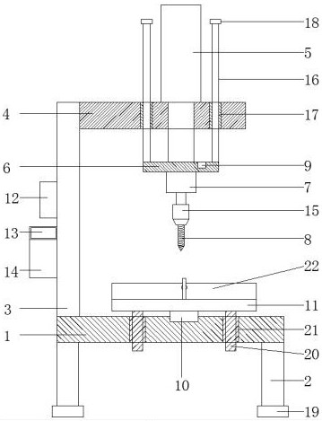
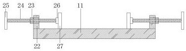
[0026] Example 1 see Figure 1-2 , according to a PLC automatic control punching device according to an embodiment of the present invention, comprising a workbench 1, support columns 2 are fixed under the four corners of the workbench 1, and a support plate 3 is fixedly arranged on one side of the workbench 1 , the inner wall of the upper end of the support plate 3 is fixed with a top plate 4, the top plate 4 is fixed with a hydraulic cylinder 5, the piston rod of the hydraulic cylinder 5 runs through the top plate 4 and the lower end is fixed with a mounting plate 6, and a motor 7 is fixed under the mounting plate 6, A drill bit 8 is fixed under the rotating shaft of the motor 7, an infrared distance measuring sensor 9 is fixedly embedded on the mounting plate 6, a limit device is provided on the mounting plate 6, a pressure sensor 10 is fixedly embedded on the workbench 1, and a pressure sensor 10 is fixedly embedded on the mounting plate 6. A bearing plate 11 is fixedly pro...

Embodiment 2

[0028] Embodiment 2 is on the basis of embodiment 1 such as figure 1 As shown, for the motor 7, the lower end of the rotating shaft of the motor 7 is fixedly equipped with a drill chuck 15, and a drill bit 8 is installed under the drill chuck 15, and the drill chuck 15 can facilitate the dismounting and installation of the drill bit 8.

Embodiment 3

[0029] Embodiment 3 is shown in Figure 1 on the basis of Embodiment 1. For the limiting device, the limiting device includes a first sliding rod 16 and a first sliding cylinder 17, and all four corners of the mounting plate 6 are fixedly installed. There are first sliding rods 16, and the top plate 4 is fixedly embedded with four first sliding cylinders 17 that match the first sliding rods 16. The first sliding cylinders 17 are respectively slidably sleeved on the corresponding first sliding rods. 16, the outer wall can make use of the limiting effect of the first sliding rod 16 and the first sliding cylinder 17 to make the mounting plate 6 move straight up and down, thereby further increasing the quality of drilling.


PUM


Abstract

The invention discloses a punching device automatically controlled by a PLC. The punching device comprises a workbench, supporting columns are fixedly arranged below the four corners of the workbench,a supporting plate is fixedly arranged on one side of the workbench, a top plate is fixedly arranged on the inner wall of the upper end of the supporting plate, a hydraulic cylinder is fixedly arranged on the top plate, a piston rod of the hydraulic cylinder penetrates through the top plate, a mounting plate is fixedly arranged at the lower end of the piston rod, a motor is fixedly arranged belowthe mounting plate, a drill bit is fixedly arranged below a rotating shaft of the motor, an infrared distance measuring sensor is fixedly embedded in the mounting plate, a limiting device is arrangedon the mounting plate, and a pressure sensor is fixedly embedded in the workbench. The punching device has the beneficial effects that automatic punching operation can be completed through the PLC, the punching depth can be accurately controlled, the punching quality is stable, and the punching efficiency is high.

Description

technical field [0001] The invention relates to the field of punching devices, in particular to a punching device automatically controlled by PLC. Background technique [0002] The drilling device is a commonly used mechanical processing equipment, which drills the workpiece through the rotation of the drill bit. In the foundry industry, castings need to be drilled, and the precision of drilling directly affects the quality of the product. The Chinese patent No. CN201620633321. The depth of punching needs to be controlled manually, which not only leads to poor depth accuracy of punching, but also the stability of punching quality is difficult to control, and the efficiency of manual punching is low. [0003] Aiming at the problems in the related technologies, no effective solution has been proposed yet. Contents of the invention [0004] The object of the present invention is to provide a PLC automatic control punching device to solve the problems raised in the above-men...

Claims


Application Information

Patent Timeline
IPC IPC(8): B23B39/08B23B39/14B23B47/00B23B47/26B23B49/00B23Q3/06
CPCB23B39/08B23B39/14B23B47/00B23B47/26B23B49/00B23Q3/06
Inventor 王岚
Owner XIAN LANXIN IND AUTOMATION ENG CO LTD
Why Eureka
Try Eureka