Vibration exciter noise isolation method
A vibration exciter and noise technology, which is applied in the field of NVH detection, can solve problems such as interference with abnormal noise testing, and achieve the effect of increasing the range of pressure changes, increasing the range of pressure changes, and stabilizing adsorption
- Summary
- Abstract
- Description
- Claims
- Application Information
AI Technical Summary
Problems solved by technology
Method used
Image
Examples
Embodiment 1
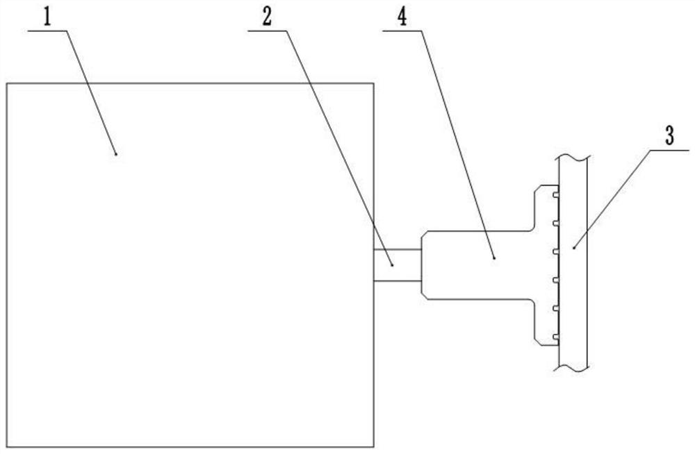
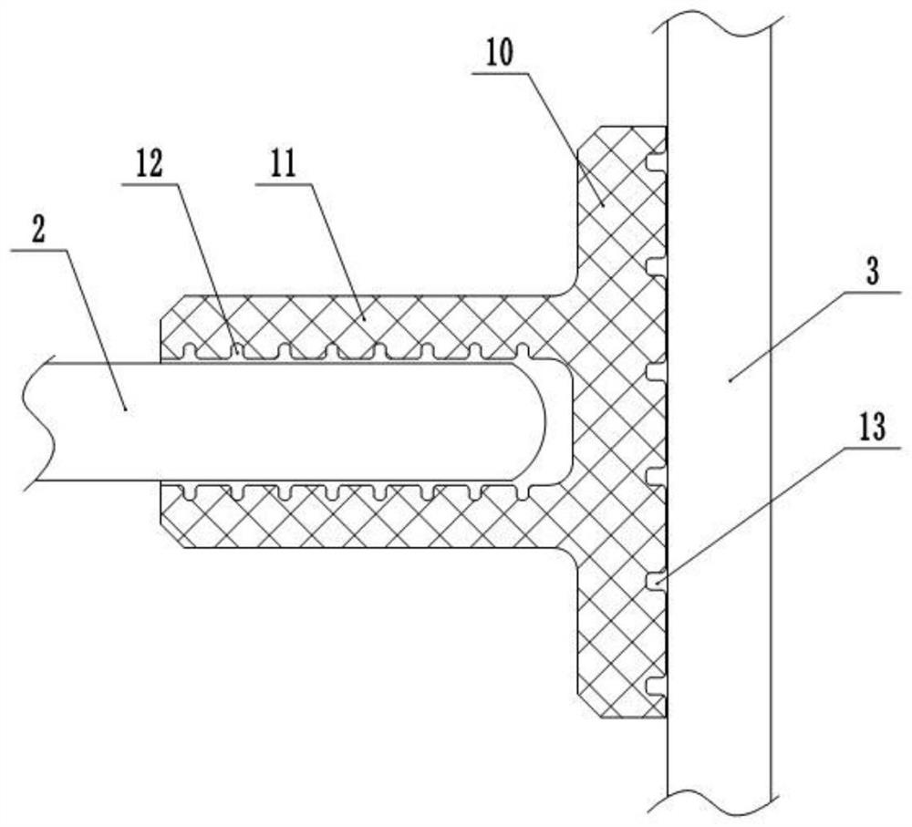
[0034] Embodiment 1 is basically as attached figure 1 with figure 2 Shown:
[0035] In the vibration exciter noise isolation method, a vibration isolation element 4 is provided between the exciter 1 and the measured object 3, because the high-frequency vibration generated by the vibrator 1 will form structural abnormal noise with the measured object 3, thereby affecting the measured object. The abnormal noise test of the test object 3, and the vibration isolation element 4 in this embodiment can isolate such high-frequency vibration.
[0036] In this embodiment, the vibration isolation element 4 includes an integrally formed rubber pad 10 and a rubber sleeve 11, wherein the rubber sleeve 11 is in interference fit with the output shaft 2 of the vibrator 1, and there are several holes on the inner wall of the rubber sleeve 11. Annular connecting grooves 12, several annular connecting grooves 12 are equally spaced, so that the output shaft 2 of the exciter 1 can better enter t...
Embodiment 2
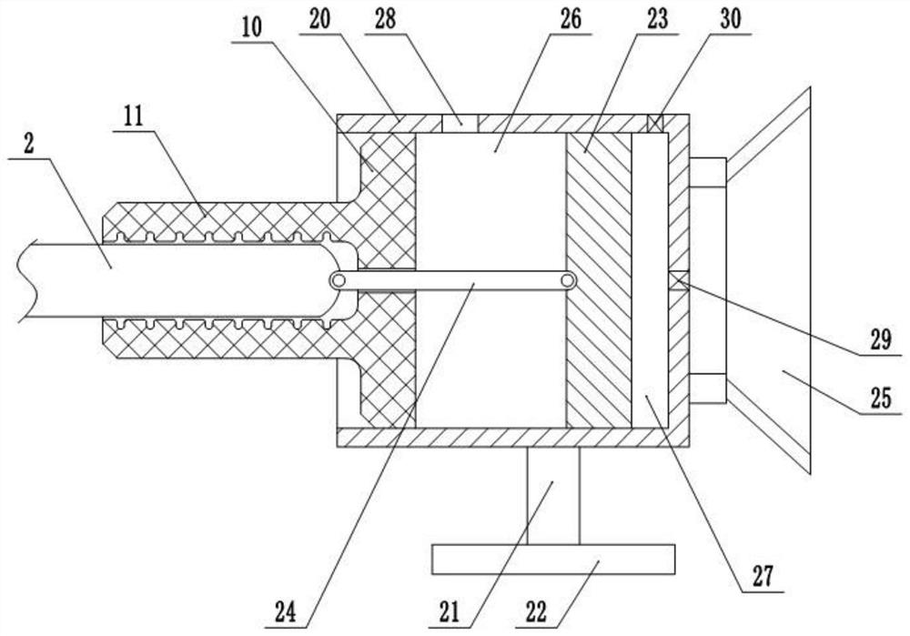
[0038] Embodiment 2 is basically as attached image 3 Shown:
[0039] The difference from Embodiment 1 is that a horizontal cylinder 20 is fixed outside the rubber pad 10, the left end of the cylinder 20 is open, and the right end of the cylinder 20 is closed. A mounting base body is fixed, and the mounting base body includes an elastic member 21 and a fixed plate 22. One end of the elastic member 21 is connected to the cylinder body 20, and the other end is connected to the fixed plate 22. In this embodiment, the elastic member 21 can be selected from a spring or a damper. A piston 23 is horizontally slidably connected in the cylinder body 20, and a through hole is opened in the middle of the rubber pad 10, and a connecting rod 24 is hinged between the piston 23 and the top of the output shaft 2, wherein the connecting rod 24 is located in the through hole.
[0040] The right end of the cylinder 20 is fixed with a suction cup 25, the opening of the suction cup 25 is set to t...
Embodiment 3
[0044] Embodiment 3 is basically as attached Figure 4 Shown:
[0045] The difference from Embodiment 2 is that a displacement expansion unit is provided in the first cavity 26, wherein the cylinder body 20 and the output shaft 2 are eccentrically arranged, that is, the central axis of the cylinder body 20 and the central axis of the output shaft 2 no longer overlap , the displacement expansion unit includes a balance bar 31, a pull rod 32 and a support base 33, wherein the support base 33 is hinged on the balance bar 31, one end of the balance bar 31 is hinged with the connecting rod 24, and the other end is hinged with the pull rod 32, and the pull rod 32 is away from the balance bar One end of 31 is hinged on the piston 23, wherein the distance between the support base 33 and the pull rod 32 is L1, the distance between the support base 33 and the connecting rod 24 is L2, L1: L2 is not less than 2, and a bracket 34 is fixed on the inner wall of the cylinder 20. The support ba...
PUM
 Abstract
Description
Claims
Application Information
 - R&D
- Intellectual Property
- Life Sciences
- Materials
- Tech Scout
- Unparalleled Data Quality
- Higher Quality Content
- 60% Fewer Hallucinations
Browse by: Latest US Patents, China's latest patents, Technical Efficacy Thesaurus, Application Domain, Technology Topic, Popular Technical Reports.
© 2025 PatSnap. All rights reserved.Legal|Privacy policy|Modern Slavery Act Transparency Statement|Sitemap|About US| Contact US: help@patsnap.com


