Non-excitation tapping switch with gear sensor
A technology of gear position sensor and tap changer, applied in electric switches, inductors, variable inductors, etc., can solve the problems of increasing the number of power outages, increasing working time and intensity, and reducing labor intensity.
- Summary
- Abstract
- Description
- Claims
- Application Information
AI Technical Summary
Problems solved by technology
Method used
Image

Examples
Embodiment 1
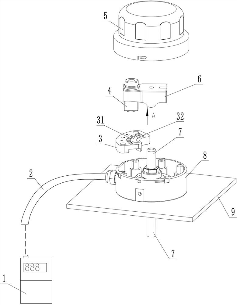
[0012] Embodiment one, see figure 1 with 2 .
[0013] It includes a transformer box cover 9, a rotating shaft 7, a handle 6 and its protective cover 5. It also includes a gear sensor. The gear sensor includes a fan-shaped sensor body 3 and a sliding contact. The sensor body is installed on the On the transformer case cover 9, promptly install protective cover seat 8 and sensor main body successively on transformer case cover 9, also sensor main body and protective cover seat can be made one and become another kind of sensor main body, preferably both are separated, facilitate manufacture. The protective cover covers the handle 6 and the gear sensor on the protective cover seat, wherein the handle is on the top and the main body of the gear sensor is down. The two internally connected sliding contacts 33 are installed on the lower surface of the handle edge through the sliding contact bracket 4, specifically the two internally connected sliding contacts 33 are installed on t...
Embodiment 2
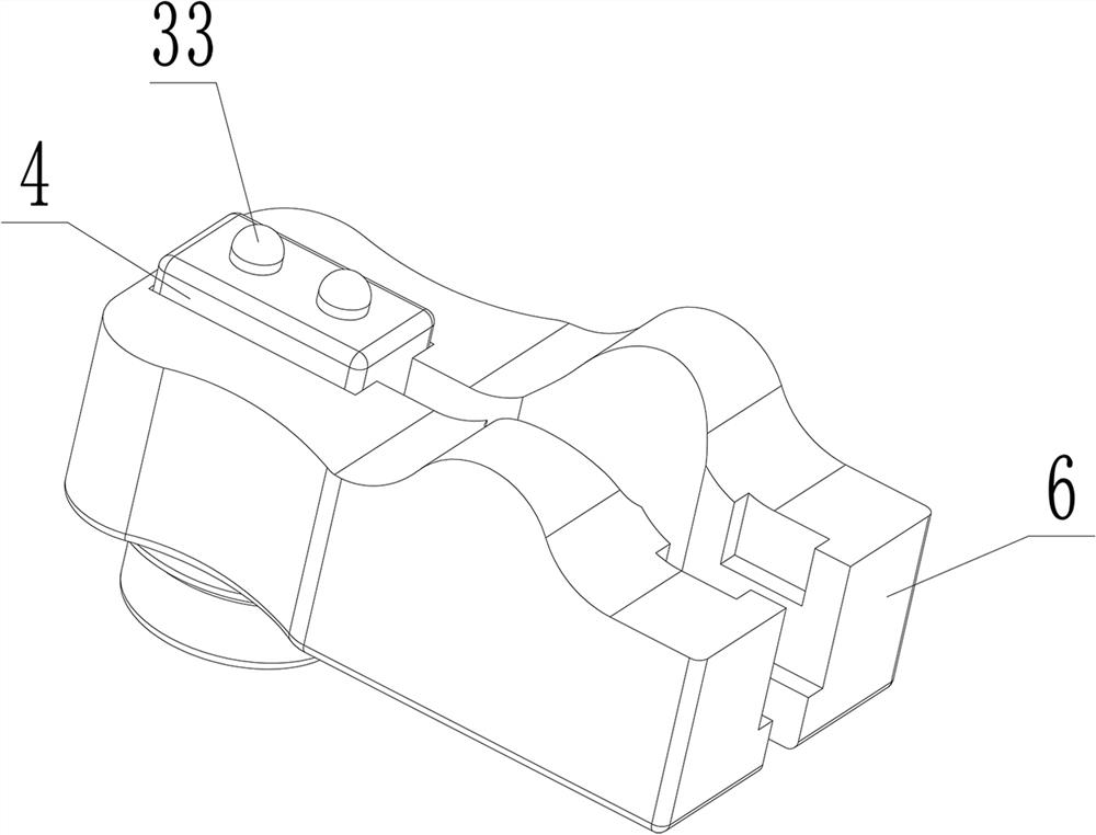
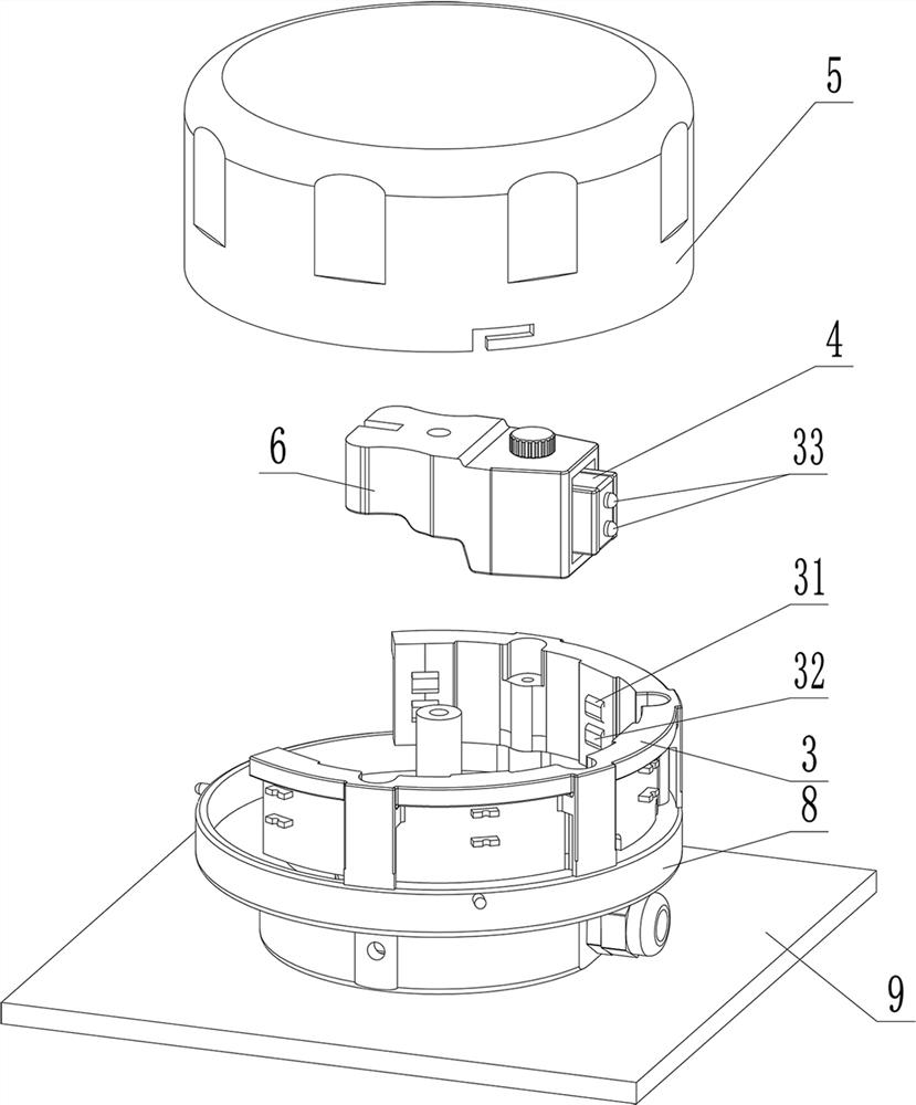
[0016] Embodiment two, see image 3 .
[0017] The difference from Embodiment 1 is that the two internally connected sliding contacts 33 are installed on the front surface of the handle edge through the sliding contact bracket 4, specifically the sliding contacts 33 are installed on the sliding contact bracket 4, and the sliding contact bracket 4. Embed in the edge of the handle from the front, so that the directions of the two sliding contacts connected inside are both forward and arranged up and down. With the movement of the handle, the moving tracks of the two sliding contacts are centered on the handle shaft A section of the same circular arc; the main body of the sensor is an arc-shaped vertical plate, installed on the protective cover seat 8, the handle shaft is located at the center of the arc of the main body of the sensor, and several static contacts and common ends of the sensor are embedded in the arc of the main body of the sensor up and down. On the inner side s...
PUM
 Abstract
Description
Claims
Application Information
 - R&D
- Intellectual Property
- Life Sciences
- Materials
- Tech Scout
- Unparalleled Data Quality
- Higher Quality Content
- 60% Fewer Hallucinations
Browse by: Latest US Patents, China's latest patents, Technical Efficacy Thesaurus, Application Domain, Technology Topic, Popular Technical Reports.
© 2025 PatSnap. All rights reserved.Legal|Privacy policy|Modern Slavery Act Transparency Statement|Sitemap|About US| Contact US: help@patsnap.com