AI intelligent panoramic camera

A panoramic camera and camera technology, applied in the field of cameras, can solve the problems of simple structure, no buffering and collision function, poor use effect, etc., and achieve the goal of helping replacement and maintenance, saving time and effort during disassembly and assembly, and good use effect. Effect

Inactive Publication Date: 2021-03-09
QINGYUAN QISHENG TECH CO LTD
View PDF1 Cites 1 Cited by
  • Summary
  • Abstract
  • Description
  • Claims
  • Application Information

AI Technical Summary

Problems solved by technology

[0003] In the Chinese utility model patent whose publication number is CN208724050U, a kind of dust-proof panoramic camera is disclosed, which includes a connecting seat, on which a rotating head is rotatably connected, and a camera cover is installed on the end of the rotating head away from the connecting seat, and the camera cover is away from the rotating head. One end of the head is fixedly connected with a middle connection cover, and a transparent cover is installed at the end of the middle connection cover away from the camera cover, a camera is installed in the camera cover and the transparent cover, and a dust-proof mechanism is installed between the transparent cover and the middle connection cover; The lower gasket seals the perforation of the transparent cover through the fixing seat, making it difficult for dust to enter the transparent cover from below. It is difficult to enter the transparent cover from the lower end or the upper end of the transparent cover, so that the imaging quality of the camera is guaranteed; but its structure is simple, the function is single, disassembly is more troublesome, time-consuming and laborious, and it does not have the function of buffering and collision, and is easy to damage. Moreover, the dust on the surface of the transparent cover cannot be cleaned, and the use effect is not good, which needs to be improved

Method used


Image

  • AI intelligent panoramic camera
  • AI intelligent panoramic camera
  • AI intelligent panoramic camera

Examples


Embodiment Construction

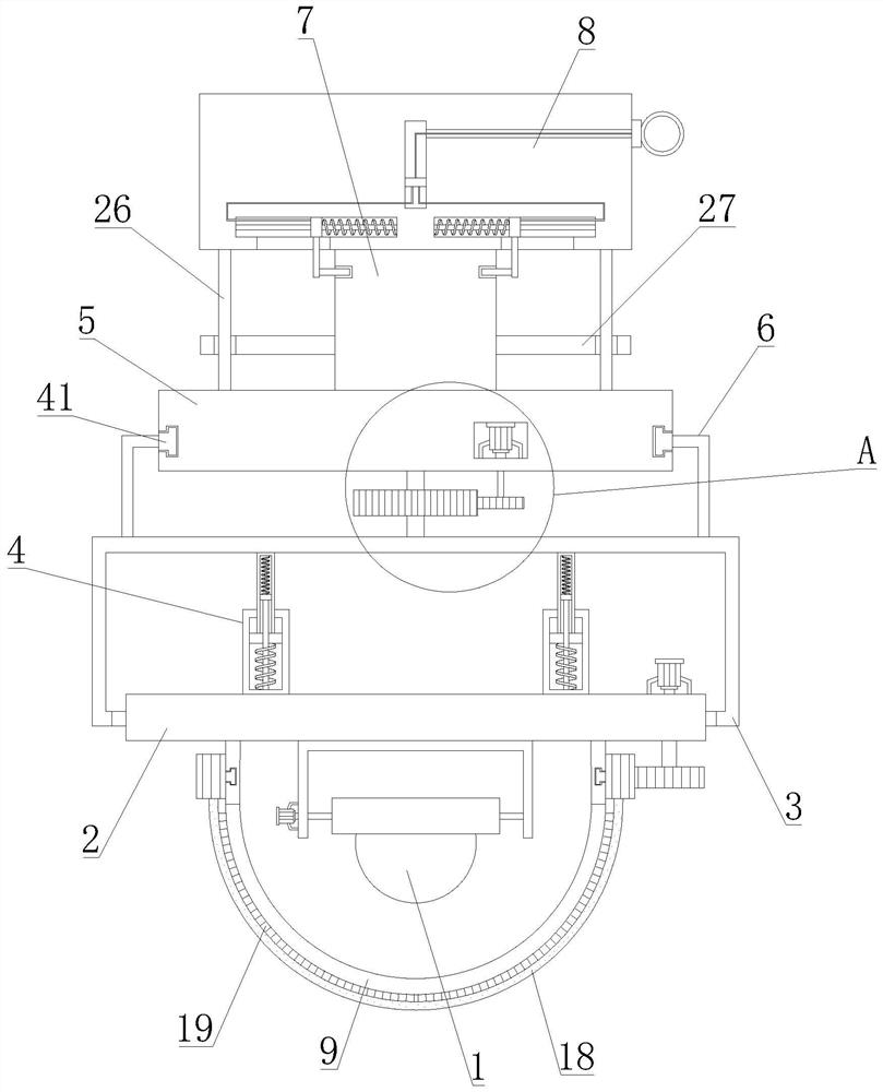
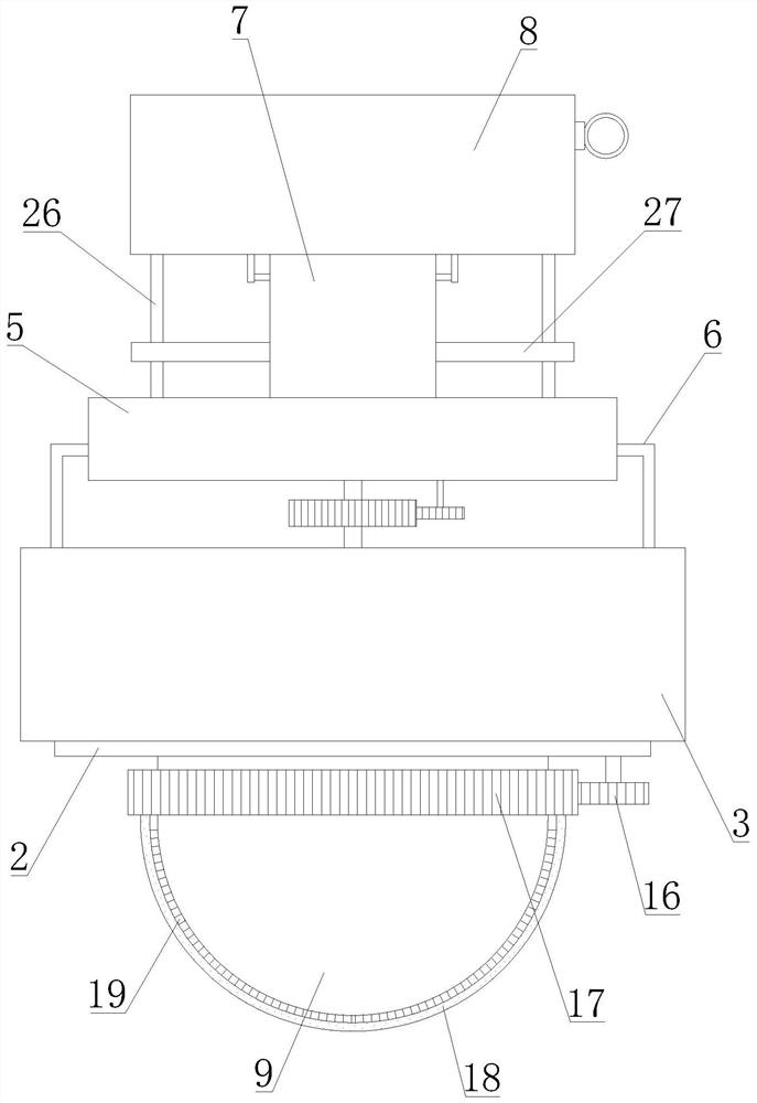
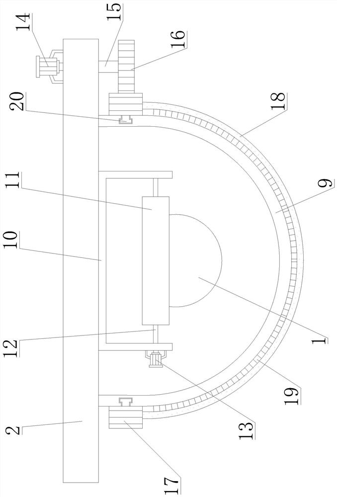
[0032] In order to make the object, technical solution and advantages of the present invention clearer, the present invention will be further described in detail below in combination with specific embodiments and with reference to the accompanying drawings. It should be understood that these descriptions are exemplary only, and are not intended to limit the scope of the present invention. Also, in the following description, descriptions of well-known structures and techniques are omitted to avoid unnecessarily obscuring the concept of the present invention.

[0033] Such as Figure 1-6 As shown, an AI intelligent panoramic camera proposed by the present invention includes a camera body 1, a movable plate 2, a connection box 3, a buffer and anti-collision device 4, a connection seat 5, a mounting seat 8, a U-shaped frame 10, and a first rotating shaft 12 , the second rotating shaft 15, the connecting shaft 21, the third rotating shaft 23, the first movable block 31, the first ...


PUM


Abstract

The AI intelligent panoramic camera comprises a camera body, A buffer anti-collision device is arranged in the connecting box and is connected with a movable plate; a transparent protective cover is arranged at the bottom of the movable plate, and the U-shaped frame is located in the transparent protective cover; the camera body is provided with a bearing plate, and the bearing plate is connectedwith the first rotating shaft. An outer gear ring is arranged on the outer peripheral surface of the transparent protective cover, and a first gear is arranged at the bottom end of the second rotatingshaft and is in meshed connection with the outer gear ring; an arc-shaped piece is arranged at the bottom of the outer gear ring, and bristles are arranged on the inner circumferential surface of thearc-shaped piece and make contact with the transparent protective cover; the connecting shaft is arranged on the connecting box and is rotationally connected with the connecting base, and a third gear is arranged on the connecting shaft; and a second gear is arranged on the third rotating shaft, and is engaged with the third gear. The dustproof, waterproof and anti-collision camera shooting device has excellent dustproof, waterproof and anti-collision performance, is convenient to disassemble and assemble, can carry out camera shooting in different directions and at different angles, can automatically clean dust on the surface of the transparent protective cover, and guarantees the camera shooting quality.

Description

technical field [0001] The invention relates to the technical field of cameras, in particular to an AI intelligent panoramic camera. Background technique [0002] Panoramic camera is a kind of camera. Camera generally has basic functions such as video recording / communication and static image capture. After collecting images through the lens, the photosensitive component circuit and control component in the camera process the image and convert it into The digital signal that can be identified is then input to the computer through the parallel port or USB connection, and then the image is restored by the software; when in use, the optical image generated by the scene through the lens (LENS) is projected onto the surface of the image sensor, and then converted to The electrical signal is converted into a digital image signal by A / D (analog-to-digital conversion), and then sent to the digital signal processing chip (DSP) for processing, and then transmitted to the computer for p...

Claims


Application Information

Patent Timeline
Patent Type & Authority Applications(China)
IPC IPC(8): H04N5/225H04N5/232G03B17/08B08B1/00B08B1/04F16M11/04F16M11/12F16M11/18F16M13/02
CPCG03B17/08B08B1/002B08B1/04F16M11/04F16M11/12F16M11/18F16M13/02H04N23/51H04N23/50H04N23/698H04N23/695
Inventor 陈其坚陈润莹
Owner QINGYUAN QISHENG TECH CO LTD
Why Eureka
Try Eureka