Transmission mechanism and mower

A technology of transmission mechanism and lawn mower, which is applied to agricultural machinery and implements, harvesters, chassis of agricultural implements, etc. It can solve the problems that lawn mowers are not widely used, and achieve the advantages of convenient operation, good stability and low center of gravity Effect

Pending Publication Date: 2021-03-12
山东禀正智慧科技有限公司
View PDF0 Cites 0 Cited by
  • Summary
  • Abstract
  • Description
  • Claims
  • Application Information

AI Technical Summary

Problems solved by technology

Due to the above reasons, lawn mowers are not widely used in agricultural production

Method used


Image

  • Transmission mechanism and mower
  • Transmission mechanism and mower
  • Transmission mechanism and mower

Examples


Embodiment 1

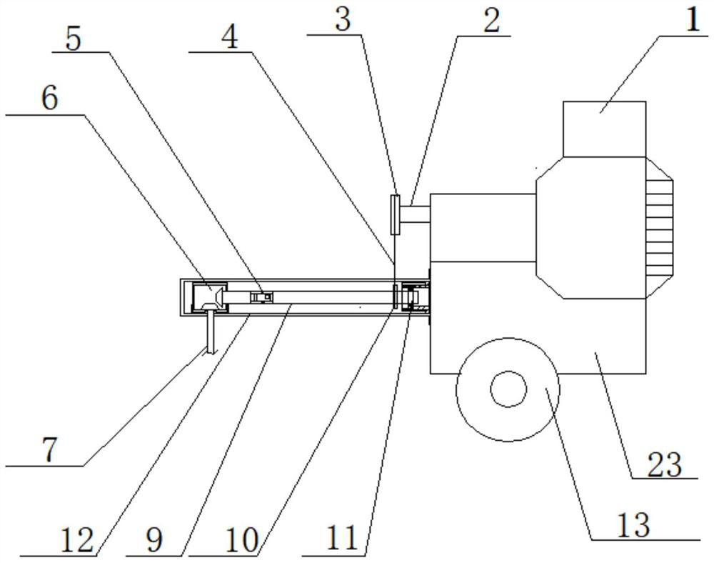
[0087] A transmission mechanism in this embodiment includes a lawnmower working part 7, a first transmission mechanism arranged horizontally, and a height adapter arranged vertically;

[0088] The output shaft 2 of the miniature agricultural machine engine is connected with the height adapter, and the end of the height adapter connected away from the output shaft 2 of the miniature agricultural machine engine is connected with the first transmission mechanism, and the end of the first transmission mechanism is far away from the height adapter. The mower working part 7 is connected; the first transmission mechanism is located below the height adapter.

[0089] The height adapter includes a first transmission wheel 3 and a second transmission wheel 10; the first transmission wheel 3 is connected to the output shaft 2 of the miniature farming machine engine, and the second transmission wheel position 10 is below the first transmission wheel 3 , is connected with the first transmi...

Embodiment 2

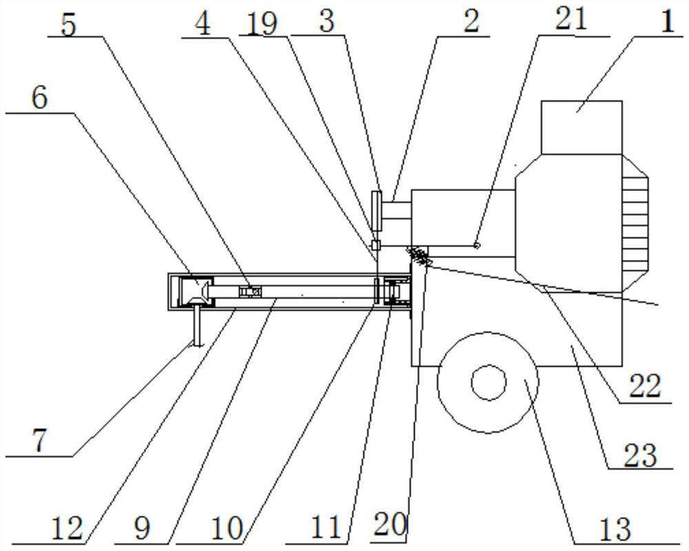
[0100] Where this embodiment is the same as Embodiment 1, no further details are given. The height adapter also includes a pulley clutch structure; the pulley clutch structure includes a belt tensioning device and a belt limiting device; the belt limiting device is arranged on Between the first transmission wheel 3 and the second transmission wheel 10 and on the outside of the transmission belt; the belt limiting device is in contact with the transmission belt 4 in a relaxed state.

[0101] The belt limiter includes two clutch columns 32, and the clutch columns 32 are arranged on the outside of the transmission belt, so that the clutch columns 32 rub against the flat surface of the transmission belt 4, the deceleration process is smooth, and there will be no sudden jam or slippage .

[0102] The belt tensioning device includes: a tensioning pulley 19, a support rod 20, a return spring 31 and a clutch pull wire 22; Under the action of the clutch pull wire 22 and the return spr...

Embodiment 3

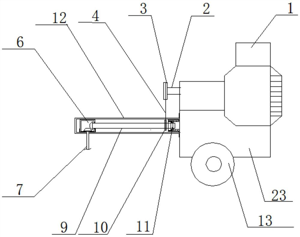
[0104] Where this embodiment is the same as Embodiment 1, no further details are given. This embodiment is a transmission mechanism, which is the same as Embodiment 1;

[0105] In the lawnmower of this embodiment, the direction of the first driven gear is opposite to that of the first driven gear in Embodiment 1.

[0106] The wheel clutch mechanism of this embodiment includes a brake drum 25 and a planetary gear set. The rotating shaft 24 passes through the brake drum 25 and the sun gear 26 of the planetary gear set in turn. The sun gear 26 and the rotating shaft 21 is fixedly connected, the inner gear ring 27 of the planetary gear set is fixedly connected with the brake drum 25, the brake drum 25 is rotationally connected with the wheel transmission shaft 24 through bearings, and the planetary gear carrier of the planetary gear set passes through The bearing is rotatably connected with the wheel drive shaft 24 and fixedly connected with the wheel.

[0107] When braking the c...


PUM


Abstract

A transmission mechanism comprises a mower working part, a first transmission mechanism and a height adapter. The height adapter is connected with the output end or the input end of the first transmission mechanism; the first transmission mechanism comprises a supporting piece and a first transmission shaft. the first transmission shaft is rotationally connected with a first connecting piece; theend, far away from the output end of a power device, of the first transmission shaft is connected with the height adapter or the mower working part through a second connecting piece; and the transmission mechanism can be suitable for most of power supply equipment, and is especially suitable for miniature farming machines widely used in rural areas at present, the problem that in agricultural production, equipment is prone to being damaged due to ground slope changes is greatly solved. The mower comprises the transmission mechanism and wheel driving mechanisms, downward movement of the overallgravity center of the mower and downward movement of the gravity centers of wheels and driving mechanisms of the wheels are achieved through the transmission mechanism and the wheel driving mechanisms, and it is guaranteed that the mower is stable and convenient to control in the moving process.

Description

technical field [0001] The invention relates to a lawn mower, in particular to a transmission mechanism and the lawn mower. Through the transmission mechanism, it is suitable for connecting a variety of power output devices to the working part of the lawn mower, especially to agricultural farming equipment. Background technique [0002] At present, there are two ways to drive the mower. One is transmitted by the power output device through the transmission shaft to drive the gearbox of the mower, or directly drives the gearbox of the mower. The cutter head rotates to achieve the purpose of mowing; the transmission shaft of another power output device extends into the body of the lawn mower and connects with the center hole of the cutter head of the lawn mower to directly drive the cutter head to rotate. [0003] However, the current transmission mode of lawn mowers cannot be widely applied to various power output devices; especially the miniature farming machines that are mo...

Claims


Application Information

Patent Timeline
Patent Type & Authority Applications(China)
IPC IPC(8): A01D69/00A01D67/00
CPCA01D67/00A01D69/00
Inventor 贾陆军翟建伟于丽娜
Owner 山东禀正智慧科技有限公司
Why Eureka
Try Eureka