
Stamping and punching die

A technology of molds and mold bases, which is applied in the direction of metal processing, etc., can solve the problems of reducing the precision of punching and punching of parts, misalignment or offset of parts, and affecting processing efficiency, so as to improve the efficiency of punching and punching and improve the precision of punching and punching , to ensure the effect of positioning accuracy

Inactive Publication Date: 2021-03-12
柏祝美
View PDF8 Cites 0 Cited by
  • Summary
  • Abstract
  • Description
  • Claims
  • Application Information

AI Technical Summary

Problems solved by technology

[0003] When stamping and punching circular sheet parts, stamping dies are also required. Generally, when stamping circular sheet parts, the circular parts are directly placed in the punching and punching area by hand. , so there is danger, and it is impossible to achieve continuous feeding, which is time-consuming and labor-intensive, and because the parts are not equipped with fixing devices during stamping, there may be misalignment or offset of parts during stamping, so The stamping and punching accuracy of the parts is greatly reduced, and sometimes the stamped parts will be lifted together with the punch, which seriously affects the processing efficiency

Method used


Image

  • Stamping and punching die
  • Stamping and punching die
  • Stamping and punching die

Examples


Embodiment Construction

[0025] In order to make the technical means, creative features, goals and effects achieved by the present invention easy to understand, the present invention will be further described below in conjunction with specific embodiments.

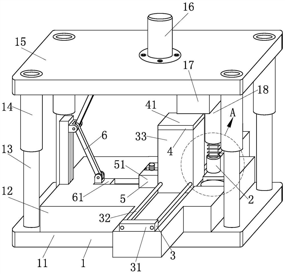
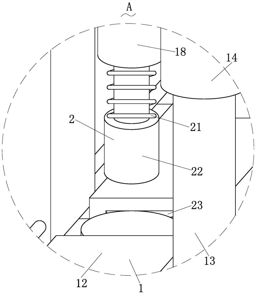
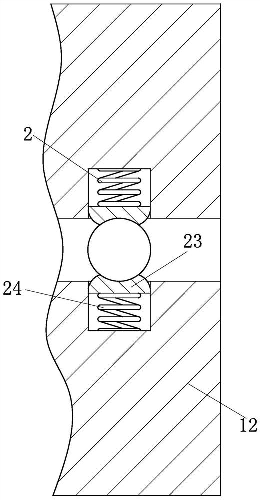
[0026] Such as Figure 1-Figure 6 As shown, a stamping punching die according to the present invention includes a punching structure 1, a pressing structure 2, a refueling structure 3, a feeding structure 4, a limiting structure 5 and a discharge structure 6, which are used for disc-shaped One end of the punching structure 1 that the parts are punched is installed with the pressing structure 2 that can press and clamp the circular parts to be punched, and one end of the punching structure 1 is set to realize The refueling structure 3 for uninterrupted feeding; the feeding structure that can press and protect the circular parts to be punched inside the refueling structure 3 is installed on the top of the refueling structure 3 4. Install the limiti...


PUM


Abstract

The invention relates to the field of dies, in particular to a stamping and punching die. The stamping and punching die comprises a punching structure, a pressing structure, a material changing structure, a feeding structure, a limiting structure and a discharging structure. Through work of the pressing structure, a part can be clamped and fixed before being punched, the part can be pressed, thusthe situation that the part deviates and is dislocated during part punching can be effectively prevented, the punching precision of the part can be greatly improved, through arrangement of the pressing structure, the discharging function can further be achieved after stamping is completed, the part can be effectively prevented from being brought up together, thus stamping and punching efficiency can be greatly improved, the material changing structure is installed at the top end of a female die, feeding work can be synchronously conducted during stamping and punching, charging time can be shortened, the production efficiency can be improved, and the limiting structure capable of limiting and fixing the material changing structure is arranged at one end of the material changing structure.

Description

technical field [0001] The invention relates to the field of dies, in particular to a stamping and punching die. Background technique [0002] Mold, various molds and tools used in industrial production for injection molding, blow molding, extrusion, die-casting or forging forming, smelting, stamping and other methods to obtain the required products. In short, a mold is a tool used to make shaped objects. This tool is composed of various parts, and different molds are composed of different parts. It mainly realizes the processing of the shape of the article through the change of the physical state of the formed material. Known as the "Mother of Industry". Under the action of external force, the blank becomes a tool with a specific shape and size. Widely used in blanking, die forging, cold heading, extrusion, powder metallurgy parts pressing, pressure casting, and compression molding or injection molding of engineering plastics, rubber, ceramics and other products. The mo...

Claims


Application Information

Patent Timeline
Patent Type & Authority Applications(China)
IPC IPC(8): B26F1/02B26F1/14B26D7/02B26D7/06
CPCB26F1/02B26F1/14B26D7/025B26D7/0608
Inventor 柏祝美李家浩
Owner 柏祝美
Learn More