Bamboo slitting equipment
A cutting and equipment technology, which is applied in the direction of mechanical equipment, thin wood chip manufacturing, wood processing equipment, etc., can solve problems such as low efficiency and affecting production, and achieve the effect of reducing workload
- Summary
- Abstract
- Description
- Claims
- Application Information
AI Technical Summary
Problems solved by technology
Method used
Image
Examples
Embodiment 1
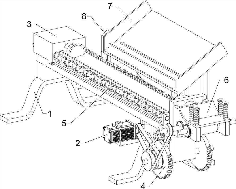
[0064] A kind of bamboo cutting equipment, such as figure 1 As shown, it includes workbench 1, motor 2, cutting mechanism 3 and driving mechanism 4. Motor 2 is connected to the right front side of workbench 1, and cutting mechanism 3 is arranged on workbench 1. Between workbench 1 and the output shaft of motor 2 A driving mechanism 4 is connected, and the driving mechanism 4 is connected with the cutting mechanism 3 .
[0065] When people need to cut bamboo into strips, the bamboo is first placed on the workbench 1, then the motor 2 is started, and the output shaft of the motor 2 rotates to drive the driving mechanism 4 to rotate, so that the parts of the cutting mechanism 3 move the wooden strips to the right, and the wooden strips Carry out cutting, people will be collected by the wooden strip after cutting, close motor 2 and get final product when not in use.
Embodiment 2
[0067] On the basis of Example 1, such as figure 2 As shown, the cutting mechanism 3 includes a sliding frame 31, a push rod 32, a guide barrel 33, a cutter 34 and a guide column 35, and the sliding frame 31 is slidably connected to the workbench 1, and the sliding frame 31 is connected with the drive mechanism 4, and slides The right side of frame 31 is connected with push rod 32, and the right side of workbench 1 top is connected with guide barrel 33, and guide barrel 33 inside is evenly provided with cutter 34, is connected with guide post 35 in the middle between cutter 34.
[0068] People place the bamboo on the right side of the push rod 32. When the parts of the drive mechanism 4 move the sliding frame 31 and the push rod 32 to the right, the bamboo moves to the right, so that the cutting knife 34 cuts the bamboo. Frame 31 and push rod 32 move to the left and reset.
[0069] The drive mechanism 4 includes a first rotating shaft 41, a first transmission wheel 42, a first...
Embodiment 3
[0072] On the basis of Example 2, such as Figure 2-5 As shown, a reset mechanism 5 is also included, and the reset mechanism 5 includes a support frame 51, a first slide bar 52 and a first spring 53, and the front and rear sides of the right side top of the workbench 1 are connected with a support frame 51. Both are connected with the first sliding rod 52, the first sliding rod 52 is slidingly connected with the sliding frame 31, the first spring 53 is connected between the front and rear sides of the right part of the sliding frame 31 and the supporting frame 51, and the first spring 53 is evenly sleeved. outside the first sliding rod 52 .
[0073] When the sliding frame 31 moves to the right, the first spring 53 is compressed, and when the first gear 46 is separated from the sector gear 44, under the action of the first spring 53, the sliding frame 31 and the push rod 32 are driven to move to the left and reset.
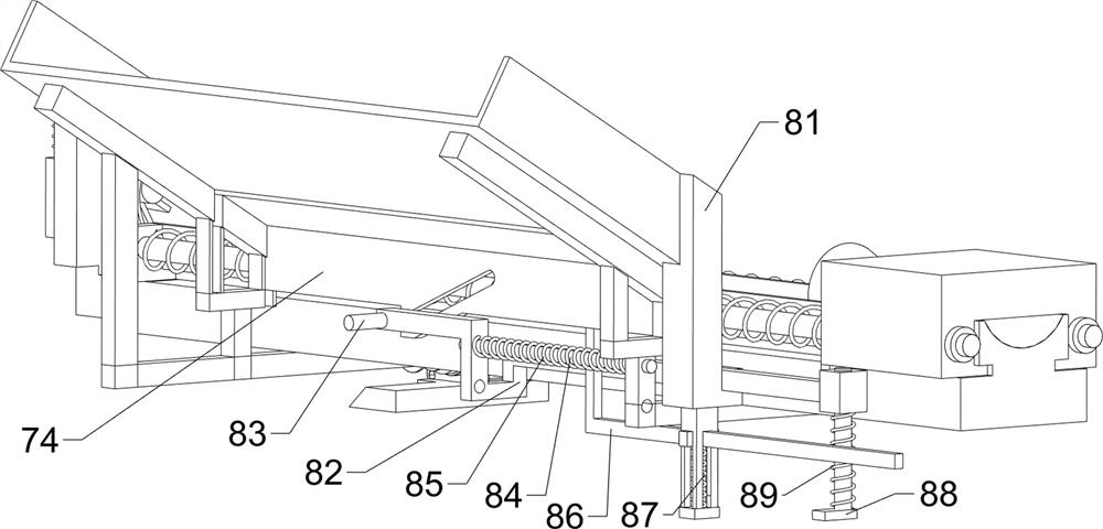
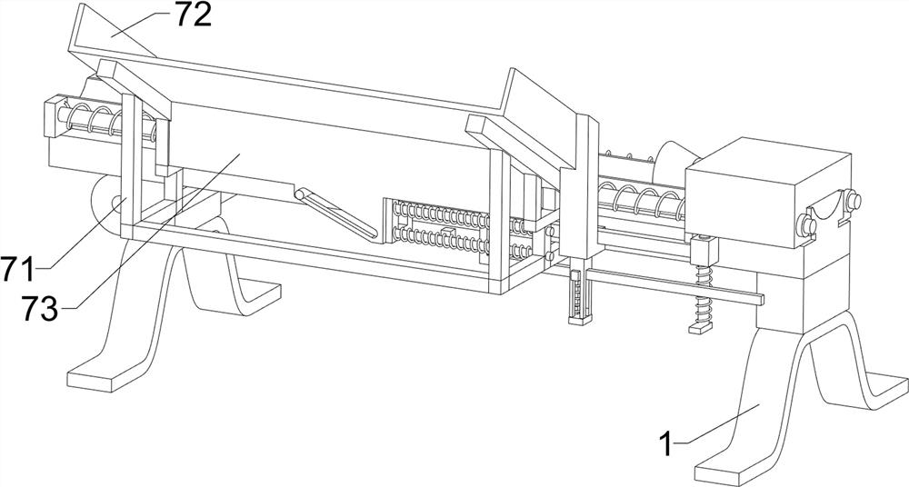
[0074] Also include material fetching mechanism 6, and mate...
PUM
 Abstract
Description
Claims
Application Information
 - R&D
- Intellectual Property
- Life Sciences
- Materials
- Tech Scout
- Unparalleled Data Quality
- Higher Quality Content
- 60% Fewer Hallucinations
Browse by: Latest US Patents, China's latest patents, Technical Efficacy Thesaurus, Application Domain, Technology Topic, Popular Technical Reports.
© 2025 PatSnap. All rights reserved.Legal|Privacy policy|Modern Slavery Act Transparency Statement|Sitemap|About US| Contact US: help@patsnap.com


