
Vehicle seat locking mechanism

A locking mechanism and vehicle seat technology, which is applied to movable seats and other directions, can solve the problems of complex structure of the locking system, weakening the structural strength of the upper rail, and heavy weight of the vehicle seat. low cost effect

Pending Publication Date: 2021-03-12
诺创汽车科技(上海)有限公司
View PDF0 Cites 1 Cited by
  • Summary
  • Abstract
  • Description
  • Claims
  • Application Information

AI Technical Summary

Problems solved by technology

Due to unreasonable structural design, the existing locking system has complex structure, many parts and high cost, which makes the weight of the vehicle seat heavier
In addition, the existing structure needs to open a large opening on the upper rail to realize the assembly of the locking system, which greatly weakens the structural strength of the upper rail

Method used


Image

  • Vehicle seat locking mechanism
  • Vehicle seat locking mechanism
  • Vehicle seat locking mechanism

Examples


Embodiment Construction

[0044] It should be noted that, in the case of no conflict, the embodiments of the present invention and the features in the embodiments can be combined with each other.

[0045] In the description of the present invention, it should be noted that the orientation or positional relationship indicated by the terms "upper", "lower", "inner", "back" and the like are based on the orientation or positional relationship shown in the drawings, and are only for It is convenient to describe the present invention and simplify the description, but does not indicate or imply that the device or element referred to must have a specific orientation, be constructed and operate in a specific orientation, and thus should not be construed as limiting the present invention. In addition, the terms "first", "second" and "third" are used for descriptive purposes only, and should not be construed as indicating or implying relative importance.

[0046] The present invention will be described in detail ...


PUM


Abstract

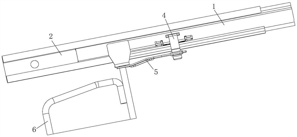
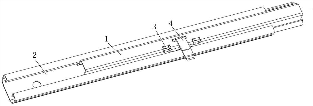
The invention relates to a vehicle seat locking mechanism that is arranged between an upper rail and a lower rail which can slide relatively and define a cavity between the upper rail and the lower rail. The vehicle seat locking mechanism comprises a torsion bar piece and a locking piece, the torsion bar piece is fixed on the upper rail and is provided with a torsion section and a free section integrally connected with the torsion section, and the free section is in a bent shape. A shaft body is included and is partially configured to be arranged side by side with the torsion section along thelength direction of the upper rail; the locking piece comprises a locking part arranged in the cavity and a force bearing part fixedly connected with the locking part, the locking part is rotatably arranged on the shaft body and locks the upper rail and the lower rail in a relative sliding mode due to the fact that the torsion section is arranged in a blocking mode, and the force bearing part isprovided with a force bearing end located outside the cavity; and the force bearing end is driven by an external force to enable the locking part to force the torsion section to twist so as to releasethe locking between the upper rail and the lower rail. Compared with the prior art, the structure is simple, the number of parts is small, the weight is low, the cost is low, and assembling is convenient.

Description

technical field [0001] The invention relates to the technical field of vehicle seats, in particular to a vehicle seat locking mechanism. Background technique [0002] At present, the driving seat of most vehicles can be adjusted forward and backward, and the adjusted seat position can be locked by a locking system. The existing locking system mainly includes an upper rail fixedly connected with the seat, a lower rail fixedly connected with the vehicle body floor, and a pawl rotatably arranged on the upper rail, and a plurality of locks are respectively formed on the upper rail and the lower rail. The tooth window, so that when the pawl is stuck in the tooth window where the upper and lower rails overlap, the locking of the relative sliding between the upper and lower rails can be realized. Due to unreasonable structural design, the existing locking system has complex structure, many parts and high cost, which makes the weight of the vehicle seat relatively heavy. In additi...

Claims


Application Information

Patent Timeline
Patent Type & Authority Applications(China)
IPC IPC(8): B60N2/08
CPCB60N2/08
Inventor 王学究周俊赵磊倪梦强李晓娜王鹏硕
Owner 诺创汽车科技(上海)有限公司
Learn More