Glass melting furnace and glass manufacturing method
A technology for glass melting furnaces and melting tanks, applied in glass manufacturing equipment, glass furnace equipment, manufacturing tools, etc., can solve problems such as energy efficiency decline, and achieve the effect of suppressing energy efficiency decline
- Summary
- Abstract
- Description
- Claims
- Application Information
AI Technical Summary
Problems solved by technology
Method used
Image

Examples
no. 1 approach ”
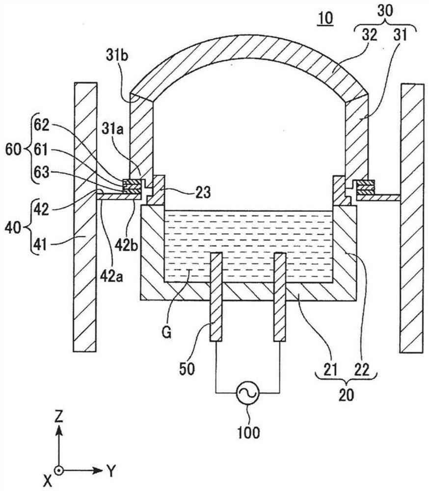
[0060] Regarding the first embodiment of the glass melting furnace of the present invention, refer to figure 1 and figure 2 Be explained.
[0061] The structure of the glass melting furnace 10 is demonstrated.
[0062] Such as figure 1 As shown, the glass melting furnace 10 of the present embodiment includes a melting tank 20 into which glass raw materials are supplied, an upper structure 30 covering the upper side of the melting tank 20 , and a plurality of energization electrodes 50 separated from each other. A supporting structure 40 is provided outside the melting tank 20 . The support structure 40 supports the upper structure 30 .
[0063] The melting tank 20 and the upper structure 30 have shapes extending in the X-axis direction. figure 1 A cross-sectional view of a plane perpendicular to the X-axis direction is shown, the X-axis direction corresponds to the longitudinal direction of the melting tank 20 , and the Y-axis direction corresponds to the width direction...
no. 2 approach ”
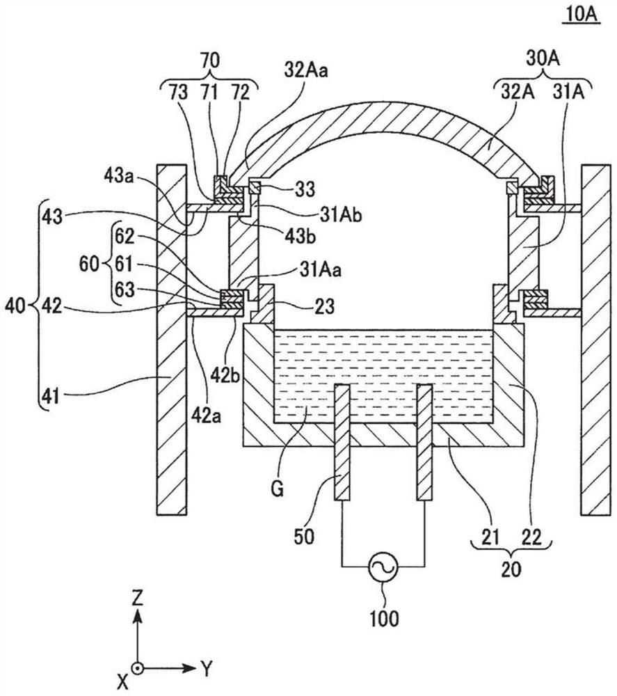
[0095] Regarding the second embodiment of the glass melting furnace of the present invention, refer to image 3 Be explained. Hereinafter, only points different from the first embodiment will be described. The structure of the upper structure and support structure of 10 A of glass melting furnaces of 2nd Embodiment differs from 1st Embodiment.
[0096] The upper structure 30A includes a horizontal wall member 31A standing upward from the side wall portion 22 of the melting tank 20 and a ceiling member 32A arranged above the horizontal wall member 31A. Such as image 3 As shown, in a section perpendicular to the X-axis direction, the lateral wall member 31A extends up and down, and the ceiling member 32A has an arched shape. The horizontal wall member 31A includes a jaw portion 31Aa at a lower end, and an extending portion 31Ab extending upward at an upper end.
[0097] Such as image 3 As shown, the high resistance refractory material 33 is provided on the upper part of t...
no. 3 approach ”
[0106] Regarding the third embodiment of the glass melting furnace of the present invention, refer to Figure 4 Be explained.
[0107] The glass melting furnace 10B of the third embodiment is different from the first embodiment in that the structure and arrangement of the energization electrodes 51 are provided on the side wall portion 22 of the melting tank 20 . The energization electrode 51 has: a planar portion 51 a having a flat surface; and a penetration portion 51 b disposed so as to penetrate the side wall portion 22 . The planar portion 51a has a plane intersecting the direction in which the penetrating portion 51b penetrates. The planar portion 51a and the penetration portion 51b are made of conductors and are electrically connected to each other. The flat part 51a of each energization electrode 51 is arrange|positioned so that molten glass G may be inserted in the melting tank 20. While the penetration part 51b of each energization electrode 51 is electrically ins...
PUM
 Abstract
Description
Claims
Application Information
 - R&D
- Intellectual Property
- Life Sciences
- Materials
- Tech Scout
- Unparalleled Data Quality
- Higher Quality Content
- 60% Fewer Hallucinations
Browse by: Latest US Patents, China's latest patents, Technical Efficacy Thesaurus, Application Domain, Technology Topic, Popular Technical Reports.
© 2025 PatSnap. All rights reserved.Legal|Privacy policy|Modern Slavery Act Transparency Statement|Sitemap|About US| Contact US: help@patsnap.com