Ultrasonic vibration and welding stick feeding system compound welding method and device thereof

An ultrasonic vibration and welding device technology, applied in welding equipment, arc welding equipment, manufacturing tools, etc., can solve the problems of energy enhancement, low ultrasonic vibration efficiency, etc., to improve the crystallization state, improve the energy distribution of the molten pool, and improve the stability. Effect

Inactive Publication Date: 2008-08-13
HARBIN INST OF TECH
View PDF0 Cites 35 Cited by
  • Summary
  • Abstract
  • Description
  • Claims
  • Application Information

AI Technical Summary

Problems solved by technology

The current problem with this method is that the ultrasonic vibration effect is related to the application position, and the ultrasonic application point must also move as the molten pool moves during the welding process.
Secondly, the size and s

Method used


Image

  • Ultrasonic vibration and welding stick feeding system compound welding method and device thereof

Examples


Embodiment 1

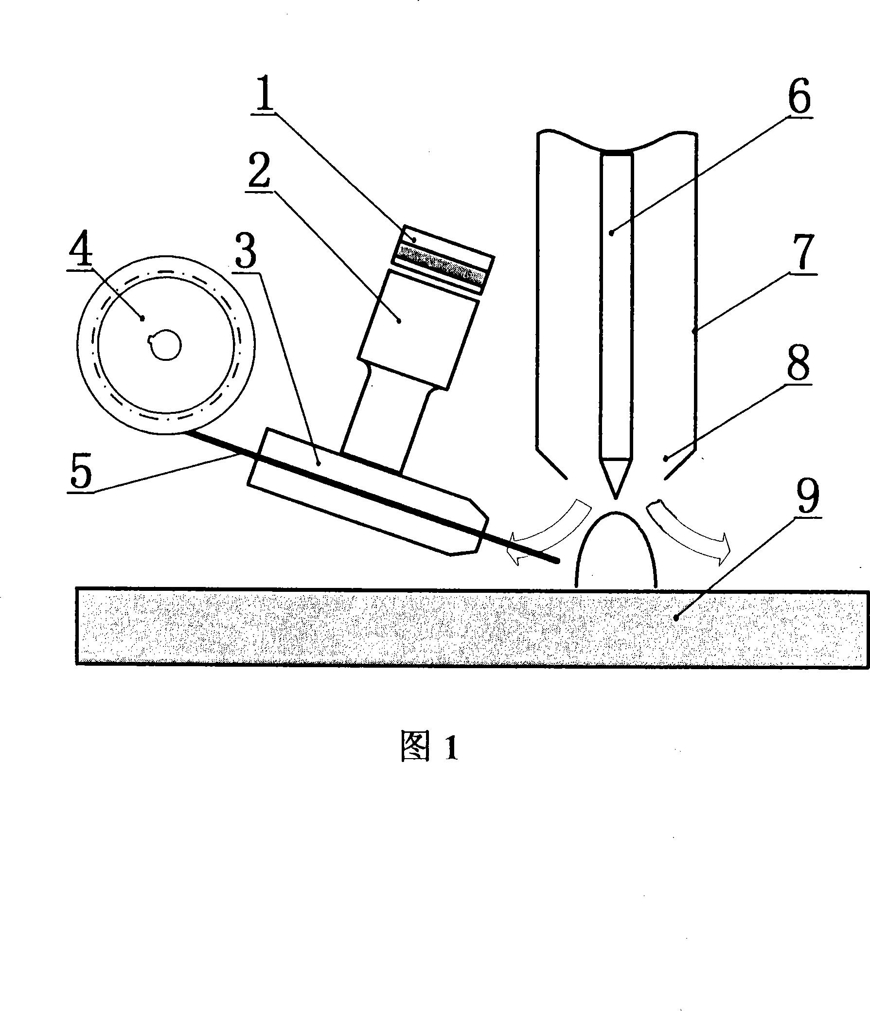
[0018] Embodiment 1, in conjunction with Fig. 1, the welding method of described supersonic wave and non-MIG arc welding welding wire feeding system compound, at first will redesign ultrasonic transducer 1 and ultrasonic horn 2, make it conform to welding wire feeding Into the complex requirements of the system. Accurately calculate the ultrasonic horn 2 to find the required node positions; reasonably combine the wire feeder 3 used for welding with the horn 2 so that the ultrasonic wave can be effectively transmitted to the welding wire 5; during welding, the arc After the start is stable, start the welding wire feeding system 4 and start the ultrasonic power supply to load the electrical signal to the ultrasonic transducer 1, convert the electrical energy into vibration through the transducer 1, amplify the ultrasonic vibration amplitude through the horn 2, and finally transmit Give wire 5.

Embodiment 2

[0019] Embodiment 2: in conjunction with Fig. 1, described a kind of welding method and its device of ultrasonic vibration and welding wire feeding system combination, the electric signal of ultrasonic power supply is converted into mechanical vibration by transducer 1, because the mechanical vibration of transducer The amplitude is small, and the horn is used to amplify it to 20μm-200μm, and finally the vibration is transmitted to the wire feed nozzle 3 embedded in the end of the horn. The above device can work under ultrasonic vibration with a frequency of 1 kHz to 2 MHz. The input power of ultrasound can be adjusted arbitrarily between 1W and 1000W. Welding is carried out according to the method of common non-melting electrode gas shielded welding. After applying ultrasound, the welding wire 5 will be subjected to the action of ultrasound, and the molten droplet will be affected by ultrasonic vibration, which helps to control the shape and size of the molten droplet during ...

Embodiment 3

[0020] Embodiment 3: in conjunction with Fig. 1, on the basis of the welding method described above, the ultrasonic vibration energy is transmitted to the welding wire 5, so that after the ordinary non-melting electrode gas shielded welding is applied with ultrasonic waves, the transition of the welding wire 5 droplet is obvious The improvement is more conducive to the transfer of droplets. In the case of small current, the size of the droplet transfer can be controlled; and the qualitative and quantitative control of the droplet transfer can be realized. On the basis of the common non-melting electrode arc welding system, the welding torch used in welding is not changed, only the ultrasonic wave is applied to the welding wire 5, and then transmitted to the molten droplet and molten pool. The method improves the efficiency of the welding arc and realizes the transformation of the traditional welding system. The ultrasonic waves transmitted through the welding wire 5 have an e...


PUM


Abstract

The invention discloses an ultrasonic vibration and welding wire feed system composite welding method and a device thereof which are provided with a stable welding process, high quality of welding seams, controllable welding pool grain growth phenomenon after welding, and high welding quality in normal welding surroundings. The objective is achieved by following steps: transmitting cavitation effect and vibration effect to the welding pool during the welding wire and welding pool contacting process by broadcasting the ultrasonic in the welding wire feed system. The melt drop size at the terminal of the welding wire is controlled effectively by ultrasonic action during welding process, transition from melt drop to welding pool is more stable, and welding seam quality is further improved. Since ultrasonic is applied in the welding feed system during welding process, welding wire melt drop transition condition is affected, energy distribution status during welding process is improved, thereby refinement and homogenization degree of the joint, and mechanical property such as intensity are further enhanced.

Description

technical field [0001] The invention relates to a welding method, which is a welding method in which ultrasonic waves are introduced into a welding wire feeding system, and belongs to the fields of non-melting electrode arc welding, arc smelting technology and arc processing. Specifically, it is a welding method and its device combining ultrasonic vibration and welding wire feeding system. technical background [0002] The welding wire feeding system is an important part of non-melting electrode arc welding. Usually, the welding wire feeding system is required to provide the necessary molten metal in welding to meet the mechanical properties in welding. Ordinary TIG welding is widely used in the welding production of various metals and their alloys. However, during the feeding process of TIG welding wire, a large amount of heat needs to be absorbed due to the extra metal melting, and the size of the molten pool during welding is too large, and the crystals after welding The...

Claims


Application Information

Patent Timeline
IPC IPC(8): B23K9/12B23K9/133
Inventor 孙清洁范成磊杨春利范阳阳
Owner HARBIN INST OF TECH
Why Eureka
Try Eureka