Sound absorption and vibration reduction floating floor ground structure for theater and construction method thereof
A floating floor, sound-absorbing technology, applied in the direction of floors, theaters, building structures, etc., can solve the problems of potential safety hazards, easy falling off of poured concrete, poor seismic performance of brick-concrete, etc., to improve safety and anti-vibration. The effect of solving the problem of vibration and sound transmission of equipment foundation
- Summary
- Abstract
- Description
- Claims
- Application Information
AI Technical Summary
Problems solved by technology
Method used
Image
Examples
Embodiment 1
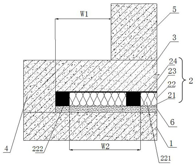
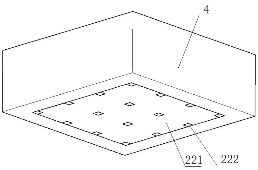
[0030] Such as Figure 1-5 As shown, the sound-absorbing and vibration-damping floating floor ground structure for theaters according to the preferred embodiment of the present invention includes a concrete floor 1 , a floating foundation structure 2 , a concrete vibration-damping foundation for equipment 3 , and hoop concrete 4 . The floating foundation structure 2 includes a first waterproof layer 21 , a floating vibration isolation cushion layer 22 , a second waterproof layer 23 and a steel plate layer 24 . The first waterproof layer 21 is arranged on the top of the concrete bottom slab 1, the floating vibration isolation cushion 22 is arranged on the top of the first waterproof layer 21, the second waterproof layer 23 is arranged on the top of the floating vibration isolation cushion 22, and the steel plate layer 24 It is arranged on the top of the second waterproof layer 23. Among them, the equipment concrete vibration damping foundation 3 is poured and formed on the top...
Embodiment 2
[0032] In a preferred embodiment, as figure 1 As shown, when the flatness of the original structural surface does not meet the requirements, it will have a great impact on the vibration reduction effect, and the ground needs to be leveled first. A ready-mixed mortar leveling layer 6 is arranged on the top of the concrete bottom slab 1, and the outer boundary of the floating foundation structure 2 is the expansion range W1 of the equipment foundation 5, which is at least 150mm. And the inner wall of the hoop concrete 4 fits with the outer wall of the floating foundation structure 2 and the equipment concrete damping foundation 3 respectively. The hoop concrete 4 is a reinforced concrete structure, and a plurality of steel bars fixedly connected with the concrete bottom plate 1 are arranged in the hoop concrete 4, thereby enhancing the overall vibration resistance and safety.
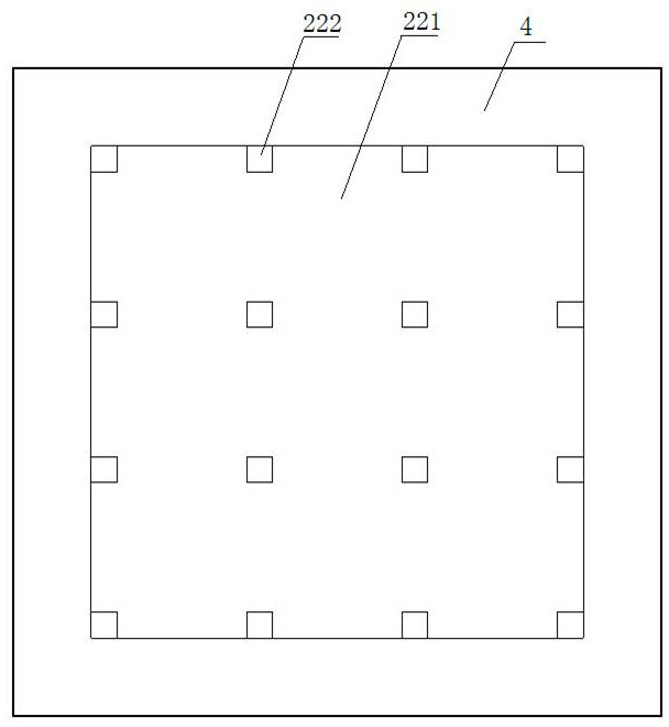
[0033] Further, the sound-absorbing glass wool 221 has a square cross-section, and the sound-absorbin...
Embodiment 3
[0038] In a preferred embodiment, the thickness of the first waterproof layer 21 and the second waterproof layer 23 are both 1 mm, and the thickness of the steel plate layer 24 is 2 mm. Ready-mixed mortar leveling layer 6 is made of C30 fine stone concrete with a thickness of 20mm. The thickness of the floating vibration isolation cushion 22 is 50mm, wherein the thickness of the sound-absorbing glass wool 221 is 50mm, 24kg / m³, and the size of the rubber pad 222 is 50mm×50mm×50mm. The distance between two adjacent vertical through holes arranged horizontally and vertically respectively is 300 mm. The cross-sectional area of the ready-mixed mortar leveling layer 6, the first waterproof layer 21, the floating vibration isolation cushion layer 22, the second waterproof layer 23 and the steel plate layer 24 is 11m 2 .
PUM
| Property | Measurement | Unit |
|---|---|---|
| Thickness | aaaaa | aaaaa |
| Thickness | aaaaa | aaaaa |
| Thickness | aaaaa | aaaaa |
Abstract
Description
Claims
Application Information
 - R&D
- Intellectual Property
- Life Sciences
- Materials
- Tech Scout
- Unparalleled Data Quality
- Higher Quality Content
- 60% Fewer Hallucinations
Browse by: Latest US Patents, China's latest patents, Technical Efficacy Thesaurus, Application Domain, Technology Topic, Popular Technical Reports.
© 2025 PatSnap. All rights reserved.Legal|Privacy policy|Modern Slavery Act Transparency Statement|Sitemap|About US| Contact US: help@patsnap.com


