Life buoy inflation detection device and method

A detection device and technology of a life buoy, which is applied to the container filling method, the container discharge method, the installation device of the container structure, etc., can solve the problem of inability to accurately judge whether the life buoy is full, the increase of the swing range of the pressure gauge value, and the inability to meet the factory requirements and other problems, to achieve the effect of shortening the inflation time, improving the control accuracy and reducing the impact

Pending Publication Date: 2021-03-12
FUZHOU UNIV
View PDF0 Cites 0 Cited by
  • Summary
  • Abstract
  • Description
  • Claims
  • Application Information

AI Technical Summary

Problems solved by technology

Due to the strict requirements of the factory on the accuracy of inflation, the existing inflation equipment cannot meet the needs of actual production, and in the process of high-pressure inflation, as the pressure increases, the phenomenon of backflow of the gas when it encounters wrinkles becomes more obvious, which makes the value of the pressure gauge swing. increase, so it is impossible to accurately judge whether the lifebuoy is full. If the lifebuoy is not full, it cannot meet the factory requirements. If the lifebuoy is over-inflated, it will cause plastic deformation of the lifebuoy, or even an explosion.

Method used


Image

  • Life buoy inflation detection device and method
  • Life buoy inflation detection device and method
  • Life buoy inflation detection device and method

Examples


Embodiment Construction

[0028] The present invention will be further described in detail below in conjunction with the accompanying drawings and specific embodiments.

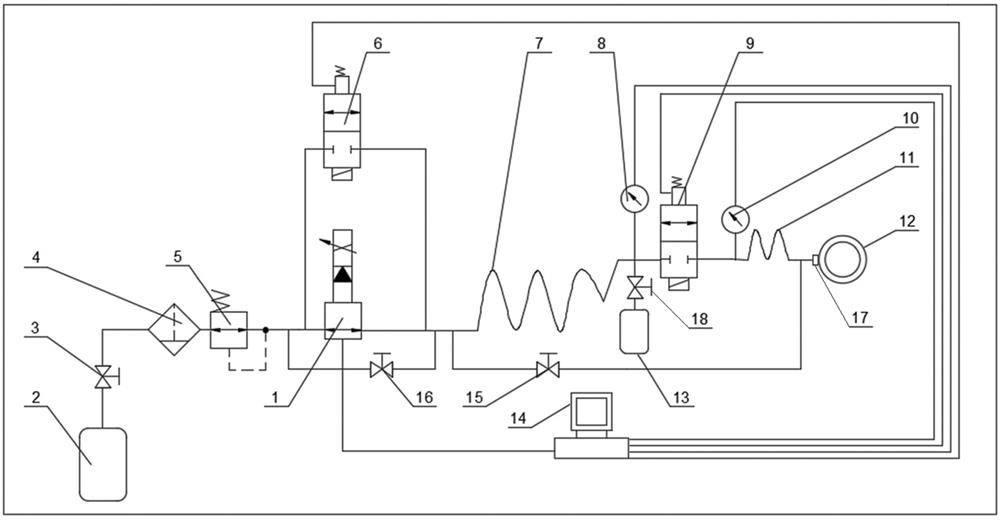
[0029] Such as figure 1 As shown, the present invention provides a lifebuoy inflation detection device, including an air source 2, a proportional solenoid valve 1, a first normally closed solenoid valve 6, a second normally closed solenoid valve 9, a first buffer air pipe 7, and a second buffer air pipe 11. Air storage tank 13, first pressure sensor 8, second pressure sensor 10, inflation nozzle 17 and industrial computer 14, the gas source 2 is connected to the intake end of the proportional electromagnetic valve 1 through the connecting air pipe, and the proportional electromagnetic valve The outlet end of the valve 1 is connected to the inlet end of the first buffer air pipe 7 through the connecting air pipe, the two ends of the proportional solenoid valve 1 are connected in parallel with the first normally closed electromagnetic v...


PUM


Abstract

The invention relates to a life buoy inflation detection device and method. The device comprises an air source, a proportional electromagnetic valve, normally closed electromagnetic valves, buffer airpipes, an air storage tank, pressure sensors, an inflation nozzle and an industrial personal computer, the air source is connected with the first buffer air pipe through the proportional electromagnetic valve, and two ends of the proportional electromagnetic valve are connected with the first normally closed electromagnetic valve in parallel; the first buffer air pipe is simultaneously connectedwith the air storage tank and the second normally closed electromagnetic valve, the other end of the second normally closed electromagnetic valve is connected with the inflation nozzle through the second buffer air pipe, the first pressure sensor and the second pressure sensor are arranged at the two ends of the second normally closed electromagnetic valve correspondingly, and the second pressuresensor, the industrial personal computer and the proportional electromagnetic valve form closed-loop feedback; and the second pressure sensor feeds back the measured inflation pressure value of a lifebuoy to the industrial personal computer, the industrial personal computer automatically adjusts the opening degree of the proportional electromagnetic valve through fuzzy PID control, and then the inflation pressure value is continuously adjusted to be close to the preset pressure value. The device and method are beneficial to improving the efficiency and the precision of air inflation, shortening the air inflation time and accurately controlling the air inflation amount.

Description

technical field [0001] The invention belongs to the technical field of inflation detection, and in particular relates to a lifebuoy inflation detection device and method. Background technique [0002] There are many types of lifebuoys, such as baby seat rings, neck floats, waist supports, etc., with different and complicated shapes, and lifebuoys have a lot of folds when they are not inflated. In the actual factory, high-pressure inflation is used to shorten the inflation time and improve the inflation efficiency. The small lifebuoy only takes 2-3 seconds to inflate, and the error must be controlled within 50 mm of water column. Due to the strict requirements of the factory on the accuracy of inflation, the existing inflation equipment cannot meet the needs of actual production, and in the process of high-pressure inflation, as the pressure increases, the phenomenon of backflow of the gas when it encounters wrinkles becomes more obvious, which makes the value of the pressure...

Claims


Application Information

Patent Timeline
Patent Type & Authority Applications(China)
IPC IPC(8): F17C5/00F17C7/00F17C13/00F17C13/02F17C13/04
CPCF17C5/005F17C7/00F17C13/002F17C13/025F17C13/04F17C2205/0302F17C2205/0326F17C2205/0329F17C2205/0394F17C2227/04F17C2250/043F17C2250/0626F17C2250/075F17C2270/0772F17C2270/079
Inventor 林正英傅国相单康康裴海
Owner FUZHOU UNIV
Why Eureka
Try Eureka