Chipless cutting device and method for steel tubes

A technology for cutting devices and steel pipes, applied in the direction of pipe shearing devices, shearing devices, maintenance and safety accessories, etc., can solve the problems of easy generation of dust, difficult radial feed pressure, and easy damage of limit pins by impact, etc., to achieve Improve production efficiency, ensure continuity, and ensure effectiveness

Inactive Publication Date: 2013-07-24
安徽华龙环保技术工程有限公司
View PDF6 Cites 0 Cited by
  • Summary
  • Abstract
  • Description
  • Claims
  • Application Information

AI Technical Summary

Problems solved by technology

[0002] According to the presence or absence of chips in the pipe cutting process, it is divided into chip cutting and chip-free cutting. Chip cutting is not only much lower in technical accuracy than chip-free cutting, but also prone to dust, especially in the process of metal cutting, dust is scattered into the air. It is accompanied by a pungent odor, which is a serious hazard to the health of the operators and pollutes the environment. Chipless cutting has become the current development direction of cutting
[0003] At present, the chipless cutting mostly uses the centrifugal force of the counterweight to pressurize and feed radially, also known as flexible locking. Rotating around the pin shaft, by adjusting the position and mass of the counterweight, the counterweight is thrown outward under the action of centrifugal force, so that the blade is fed radially to cut the steel pipe, and the lower limit pin and upper limit pin play the role of limit. Tension spring reset; but the radial feed pressure of this scheme is unstable, and it is difficult to achieve effective radial feed pressure; the limit pin is easily damaged by impact; it is easy to produce flash burrs

Method used


Image

  • Chipless cutting device and method for steel tubes

Examples


Embodiment Construction

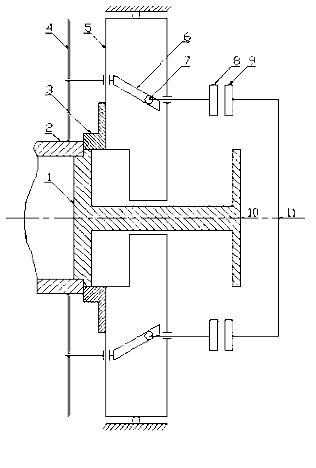
[0018] Referring to the accompanying drawings, a chipless cutting device for steel pipes includes a linear motor I 10 and a linear motor II 11, a thrust bearing seat I 8 and a thrust bearing seat II9, two inclined blocks 6, a hollow main shaft 5, a positioning plate 1, two Only the roller 7 and two blades 4, the inclined block is arranged inside the hollow main shaft, the blade is connected with the hollow main shaft, the inclined block is movably connected with the thrust bearing seat through the roller, the thrust bearing seat is connected with the linear motor, and the positioning plate is connected with the other A linear motor is connected, and the two blades, the two inclined blocks, the two rollers and the two sets of thrust bearing seats are arranged symmetrically along the center of the hollow main shaft.

[0019] The chipless cutting device for steel pipes also includes a discharge plate 3, which is arranged at one end of the hollow main shaft and is movably connected...


PUM


Abstract

The invention discloses a chipless cutting device for steel tubes. The device comprises linear motors, a trust bearing pedestal, an oblique block, a hollow main shaft, a positioning plate, a roller and two blades. The oblique block is arranged inside the hollow main shaft. The blades are connected with the hollow main shaft. The oblique block is moveably connected with the trust bearing pedestal through the roller. The trust bearing pedestal is connected with one linear motor, and the positioning plate is connected with the other linear motor. The chipless cutting method for steel tubes comprises the following steps of: 1, starting a tube cutter; 2, positioning; 3, feeding; 4, clamping; 5, cutting; 6, resetting; and 7, discharging and circulating. The production efficiency is effectively improved, the power source is protected effectively, and the service life of a transmission system is improved effectively.

Description

technical field [0001] The invention belongs to machining equipment and a production process, in particular to a chipless cutting device for steel pipes and the production process. Background technique [0002] According to the presence or absence of chips in the pipe cutting process, it is divided into chip cutting and chip-free cutting. Chip cutting is not only much lower in technical accuracy than chip-free cutting, but also prone to dust, especially in the process of metal cutting, dust is scattered into the air. It is accompanied by a pungent odor, which is a serious hazard to the health of the operators and pollutes the environment. Chipless cutting has become the current development direction of cutting. [0003] At present, the chipless cutting mostly uses the centrifugal force of the counterweight to pressurize and feed radially, also known as flexible locking. Rotating around the pin shaft, by adjusting the position and quality of the counterweight, the counterwei...

Claims


Application Information

Patent Timeline
Patent Type & Authority Applications(China)
IPC IPC(8): B23D21/00B23D19/04B23Q11/00
Inventor 权岚
Owner 安徽华龙环保技术工程有限公司
Why Eureka
Try Eureka