
Tunnel model test device and test method capable of controlling soil loss rate

A technology of tunnel model and test device, which is applied in the direction of measuring device, soil material test, and the use of stable tension/pressure test material strength, etc., which can solve the problems of limited reference value, soil loss, and no soil loss involved. Achieve effective control of soil loss rate, convenient operation, and easy access

Pending Publication Date: 2021-03-12
SHANDONG JIANZHU UNIV
View PDF2 Cites 4 Cited by
  • Summary
  • Abstract
  • Description
  • Claims
  • Application Information

AI Technical Summary

Problems solved by technology

[0004] At present, the inventors have found that most of the existing tunnel test models use self-made small shield machines to simulate the excavation process until the tunnel is formed. For example, the patent with the publication number CN107091633A simulates the excavation process of the shield machine by propelling thin steel pipes. However, it does not involve the soil loss caused by construction factors during shield excavation
To solve the problem of soil loss caused by uneven construction or grouting under real working conditions, the patent publication No. CN111103192A proposes to use a water-filled deformation control device to wrap around the pipeline, and dynamically simulate tunnel excavation by pumping water. Although the interaction with the surrounding rock can simulate the soil loss during the excavation process, it cannot control the soil loss rate, and does not consider the obvious soil arch effect that may occur in the experimental device during the experiment. Limited reference value

Method used


Image

  • Tunnel model test device and test method capable of controlling soil loss rate
  • Tunnel model test device and test method capable of controlling soil loss rate
  • Tunnel model test device and test method capable of controlling soil loss rate

Examples


Embodiment Construction

[0040] It should be noted that the following detailed description is exemplary and intended to provide further explanation of the present invention. Unless defined otherwise, all technical and scientific terms used herein have the same meaning as commonly understood by one of ordinary skill in the art to which this invention belongs.

[0041]It should be noted that the terminology used here is only for describing specific embodiments, and is not intended to limit exemplary embodiments according to the present invention. As used herein, unless the invention clearly states otherwise, the singular form is also intended to include the plural form. In addition, it should also be understood that when the terms "comprising" and / or "comprising" are used in this specification, their Indicate the presence of features, steps, operations, means, components and / or combinations thereof;

[0042] For the convenience of description, if the words "up", "down", "left" and "right" appear in the...


PUM


Abstract

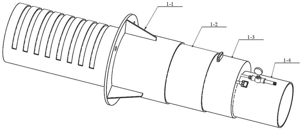
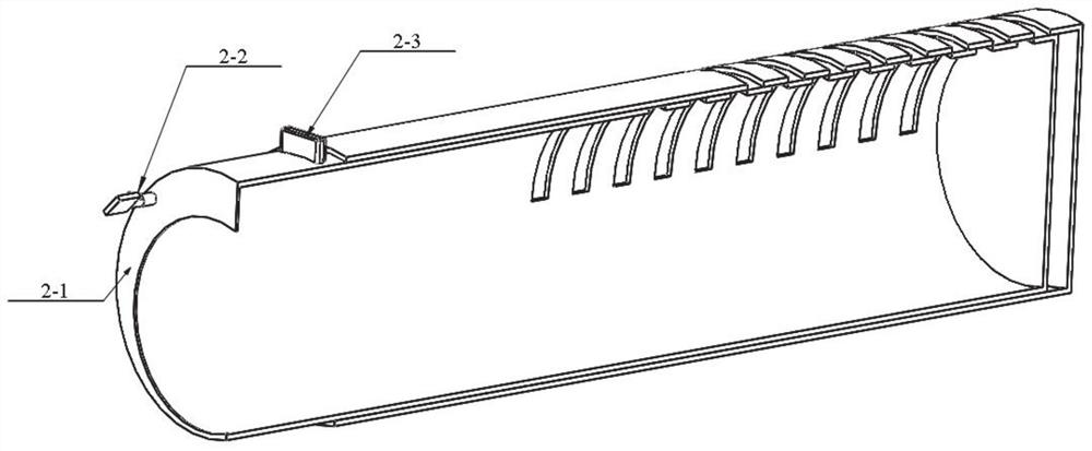
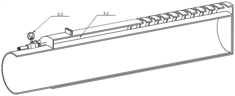
The invention discloses a tunnel model test device and test method capable of controlling the soil loss rate, which solve the problem that the soil loss rate cannot be controlled in the prior art, andhave the beneficial effect of accurately controlling the soil loss rate. The following specific scheme is adopted: the device comprises a tunnel main body structure module and a hydraulic control module; the tunnel main body structure module comprises a multi-stage sleeve structure provided with at least three sleeves, the multi-stage sleeve structure can be installed in a model test box, the innermost sleeve in the multi-stage sleeve structure is annularly closed, the multiple sleeves except the innermost sleeve are arranged in a hollowed-out mode, and in the moving process, every two adjacent sleeves can be communicated, so that sand in the model test box enters the multi-stage sleeve structure; and the hydraulic control module comprises a thin film sealing bin internally provided withliquid, the thin film sealing bin is arranged on the outer side of the innermost sleeve in the multi-stage sleeve structure, and the liquid in the thin film sealing bin can flow out of the multi-stagesleeve structure.

Description

technical field [0001] The invention relates to the field of civil engineering model tests, in particular to a tunnel model test device and a test method with controllable soil loss rate. Background technique [0002] The statements in this section merely provide background information related to the present invention and do not necessarily constitute prior art. [0003] As an important role in alleviating ground traffic pressure and energy conservation and emission reduction, subway construction has become an indispensable link in the process of urban construction and development. With the development and construction of urban underground rail transit, subway construction will have an impact on the surrounding environment. Since most of the subway tunnels pass through the central area with dense buildings, the ground loss during the construction process, the change of surrounding pore water pressure, and the deformation of the shield segment lining will all lead to the red...

Claims


Application Information

Patent Timeline
Patent Type & Authority Applications(China)
IPC IPC(8): G01N3/12G01N3/02G01N3/06G01N33/24
CPCG01N3/12G01N3/02G01N33/24G01N3/06G01N2203/0019G01N2203/0046G01N2203/0075G01N2203/0234G01N2203/0676
Inventor 魏焕卫郑晓王介鲲高祥荣李敏陈朝伟李传斌宋鹏
Owner SHANDONG JIANZHU UNIV
Learn More