Polycrystalline silicon ingot furnace and method

A technology for polycrystalline silicon ingots and ingot casting furnaces, which is applied to the growth of polycrystalline materials, chemical instruments and methods, crystal growth, etc. The effect of losing speed, improving product quality, and large market value

Pending Publication Date: 2018-01-16
河南省博宇新能源有限公司
View PDF6 Cites 2 Cited by
  • Summary
  • Abstract
  • Description
  • Claims
  • Application Information

AI Technical Summary

Problems solved by technology

[0004]In addition, since the production process of polysilicon is divided into the full-melt ingot casting process and the semi-melt ingot casting process, both of them completely control the thermal field during the ingot casting process. Different, the existing technology does not have the technology to switch between the two processes on the same equipment. In addition, due to the insensitive regulation of the thermal field, the thermal field distribution cannot effectively control the grain size and crystal growth direction of the crystal direction. , so the production quality is in a bottleneck state, and further breakthroughs cannot be made, which also leads to the inability to meet the rapid development of photovoltaic cell and other industries. Therefore, it is necessary to improve the structure and process of the existing ingot furnace, so as to improve the quality of polysilicon products

Method used


Image

  • Polycrystalline silicon ingot furnace and method
  • Polycrystalline silicon ingot furnace and method
  • Polycrystalline silicon ingot furnace and method

Examples


Embodiment Construction

[0021] The specific implementation manners of the present invention will be described in detail below in conjunction with the accompanying drawings.

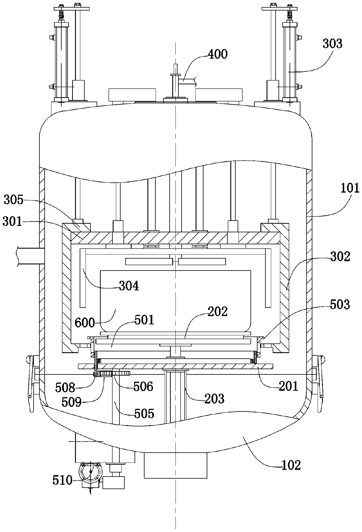
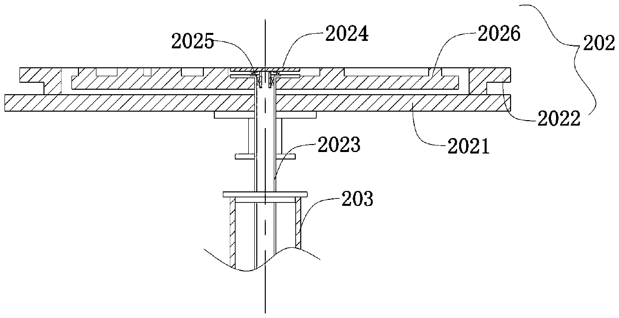
[0022] see Figure 1-Figure 5 , a polysilicon ingot casting furnace in this application, including a furnace body, a support platform 200, a heating chamber 300, a control system and an exhaust system 400; wherein the furnace body includes an upper furnace body 101 and a lower furnace body that are matched and buckled correspondingly Body 102, and between the upper furnace body 101 and the lower furnace body 102, an opening and closing power mechanism for opening and closing up and down is provided. The opening and closing power mechanism in this embodiment can be a screw and a motor that drive the lower furnace body to move up and down. Or drive the lead screw and motor of the upper furnace body and the lower furnace body action at the same time, and a hasp is also arranged between the upper furnace body and the lower furnace b...


PUM


Abstract

The invention belongs to the technical field of polycrystalline silicon production, and particularly relates to a polycrystalline silicon ingot furnace and a method. The polycrystalline silicon ingotfurnace comprises a furnace body, a supporting platform, and a heating chamber; the furnace body comprises an upper furnace body and a lower furnace body which match each other and are correspondinglyfastened, and an opening and closing power mechanism for carrying out vertical opening and closing actions is arranged between the upper furnace body and the lower furnace body; the supporting platform comprises a lower thermal insulation plate, a supporting plate, and a supporting post, the lower thermal insulation plate and the supporting plate are arranged in parallel in the lower furnace bodyat intervals, the supporting post is used for connecting and supporting the lower thermal insulation plate, the supporting plate and the lower furnace body, and a crucible is arranged on the supporting platform. The application can generate dynamic and variable thermal field distribution in the process of on-line production, consequently, thermal field distribution can be adjusted according to process requirement, and thereby the grain size of a product and the crystal orientation perpendicularity are greatly increased; the application can also effectively control the speed of heat loss, andcan carry out real-time adjustment, so that a better crystallization environment can be provided for the quality of polycrystalline silicon, consequently, the further development of the related industry is satisfied, and the application has high market value.

Description

technical field [0001] The invention belongs to the technical field of polysilicon production, and in particular relates to a polysilicon ingot casting furnace and method. Background technique [0002] There are a large number of grain boundaries in cast polysilicon, and the clean grain boundaries are non-electrically active, which has no or only a slight impact on the minority carrier lifetime, while the segregation or precipitation of impurities will change the electrical activity of the grain boundaries, which will significantly reduce Minority carrier life, the more grain boundaries, the greater the impact; but studies have shown that if the grain boundaries are perpendicular to the device surface, the grain boundaries have little effect on the electrochemical performance of the material, so increasing the grain size and improving the growth direction are important An effective method to improve the quality of polysilicon ingots. [0003] Polysilicon ingot casting furna...

Claims


Application Information

Patent Timeline
IPC IPC(8): C30B28/06C30B29/06
Inventor 王岩房灵辉
Owner 河南省博宇新能源有限公司
Why Eureka
Try Eureka