
Transformer modeling method suitable for low-voltage side pulse signal injection of distribution transformer

A technology of distribution transformers and pulse signals, which is applied in the direction of instruments, electrical digital data processing, and special data processing applications, etc., and can solve problems such as not reflecting the magnetic coupling relationship between phase and phase, inapplicability, and complexity

Active Publication Date: 2021-03-12
YUNNAN POWER GRID CO LTD LINCANG POWER SUPPLY BUREAU
View PDF8 Cites 0 Cited by
  • Summary
  • Abstract
  • Description
  • Claims
  • Application Information

AI Technical Summary

Problems solved by technology

The main problems are: (1) The current high-frequency model of the three-phase transformer is directly considered to be composed of three independent single-phase transformer models in some literatures, which does not reflect the magnetic coupling relationship between phases and may not It is suitable for single-phase and two-phase injected pulses; (2) The transformer model derived from the dual principle that embodies the three-phase magnetic coupling relationship is mostly used at low frequencies, and a concentrated capacitance parameter is often used to express the capacitive coupling relationship. It is not very accurate for high-frequency pulses; (3) For three-phase transformers, the port model based on the black box method needs to be measured multiple times, and the function fitting also needs to be multiple times, which is too complicated and cumbersome

Method used


Image

  • Transformer modeling method suitable for low-voltage side pulse signal injection of distribution transformer
  • Transformer modeling method suitable for low-voltage side pulse signal injection of distribution transformer
  • Transformer modeling method suitable for low-voltage side pulse signal injection of distribution transformer

Examples


example

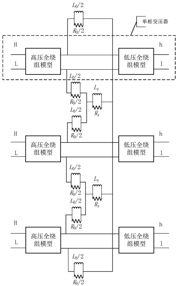
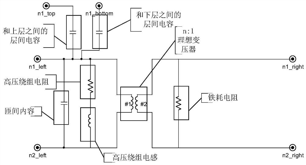
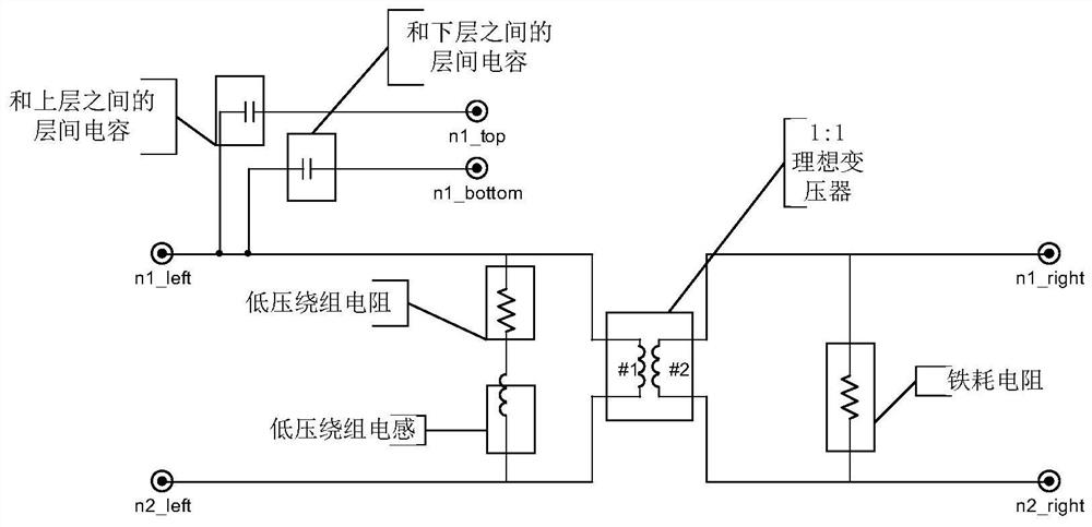
[0058]The actual structure of the S13-M-200 / 10 distribution transformer connected by Dyn11 is used to model according to the method of the present invention. The distribution transformer has a total of 13 layers of high-voltage windings, and a total of three low-voltage winding coils, each of which contains 11-layer, 11-layer and 12-layer coils. Therefore, the full-winding model of the high-voltage coil consists of 13 high-voltage winding unit models connected in series, and the full-winding model of the low-voltage coil consists of 34 low-voltage winding unit models connected in series. The interlayer capacitance, interturn capacitance, high and low voltage winding inductance and resistance can be calculated according to the actual structure, and the iron loss resistance can be calculated according to the nameplate. Bring the parameters into the high-voltage winding unit model and the low-voltage winding unit model respectively, then connect 13 high-voltage winding unit model...


PUM


Abstract

The invention relates to a transformer modeling method suitable for low-voltage side pulse signal injection of a distribution transformer, and belongs to the technical field of power transformer modeling. The method comprises the following steps: firstly, starting from the perspective of a three-phase transformer magnetic circuit, considering a magnetic coupling relationship between phases duringsingle-phase or two-phase injection, and establishing a three-phase overall model of the transformer based on a duality principle; considering the high-frequency characteristics of the transformer during pulse injection, respectively establishing a high-voltage winding unit model and a low-voltage winding unit model according to a certain principle, forming full-winding models of high-voltage andlow-voltage windings by the winding unit models, forming a single-phase transformer by the full-winding models of the high-voltage and low-voltage windings, and finally forming a three-phase integralmodel by the single-phase transformer. According to the method, the magnetic coupling relation between phases of the three-phase transformer is considered, the high-frequency characteristic during pulse injection and the high efficiency of model establishment are considered, the obtained model is finer and more accurate than a common model, and the method is suitable for the situation that pulse signals are injected into a single phase or two phases of the low-voltage side of the distribution transformer.

Description

technical field [0001] The invention belongs to the technical field of power transformer modeling, and in particular relates to a transformer modeling method suitable for injection of pulse signals at the low-voltage side of distribution transformers. Background technique [0002] The pulse signal is injected into the low-voltage side of the distribution transformer. Using the electromagnetic transmission function of the distribution transformer, the injected signal propagates in the distribution network line, and the fault location of the distribution line can be realized through the corresponding characteristic signal. Among them, the transmission analysis of the high-voltage and low-voltage side pulse signals must be carried out first, and the electromagnetic transient transmission model of the distribution transformer that injects pulse signals into the low-voltage side and then coupled to the high-voltage side is established. [0003] At present, the methods for modelin...

Claims


Application Information

Patent Timeline
IPC IPC(8): G06F30/3323
CPCG06F30/3323Y02E60/00
Inventor 刘红文李文张春丽黄继盛李佳何治海曾嘉凯
Owner YUNNAN POWER GRID CO LTD LINCANG POWER SUPPLY BUREAU
Learn More