
Electronic tag for preventing management and control equipment from flowing

An electronic label and equipment technology, which is applied to record carriers, instruments, and computer parts used in machines, can solve the problems that criminals are easy to forge, and it is difficult for prosecutors to inspect visually. effect of work

Inactive Publication Date: 2021-03-12
HANGZHOU KUANFU TECH
View PDF1 Cites 0 Cited by
  • Summary
  • Abstract
  • Description
  • Claims
  • Application Information

AI Technical Summary

Problems solved by technology

[0006] The purpose of the present invention is to solve the problem that the existing electronic labels that prevent the flow of control equipment are easy to be faked by lawbreakers and difficult for inspectors to visually inspect. The present invention provides an electronic label that prevents the flow of control equipment

Method used


Image

  • Electronic tag for preventing management and control equipment from flowing
  • Electronic tag for preventing management and control equipment from flowing
  • Electronic tag for preventing management and control equipment from flowing

Examples


Embodiment 1

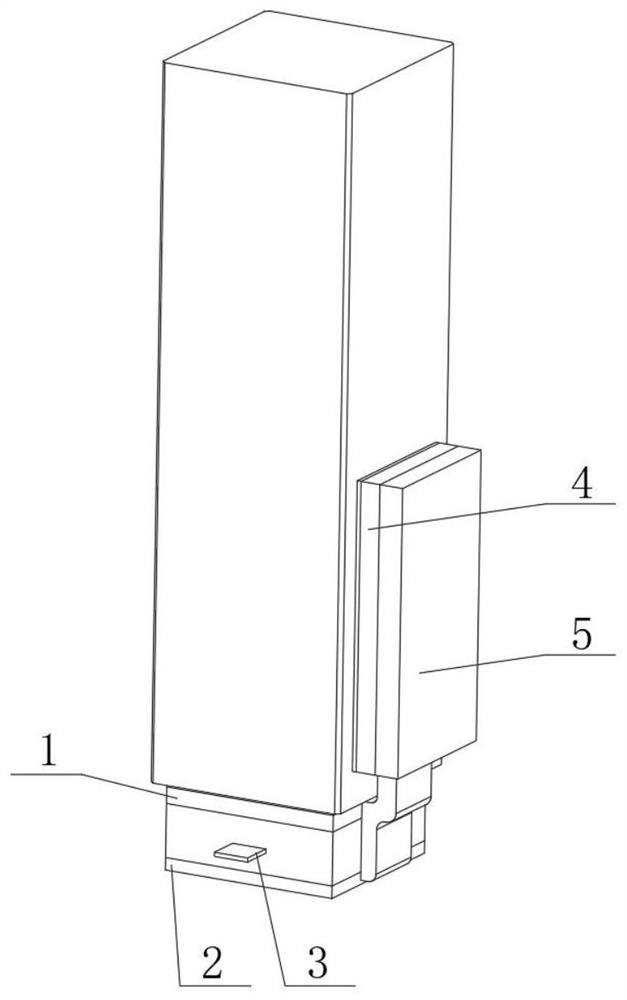
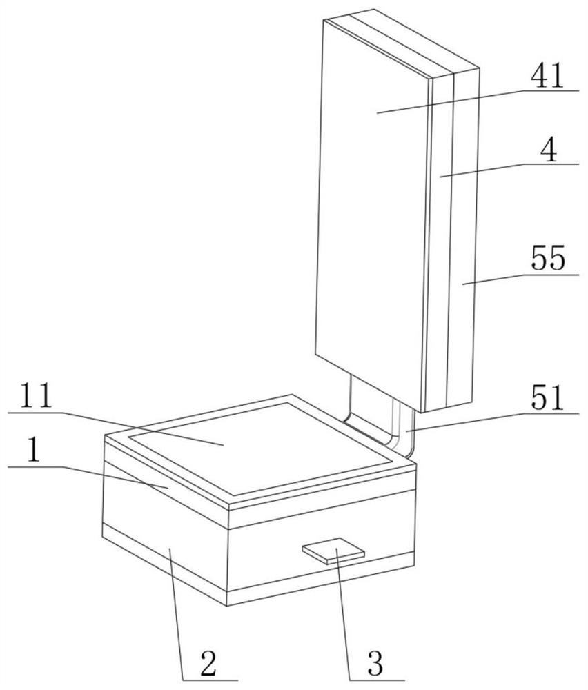
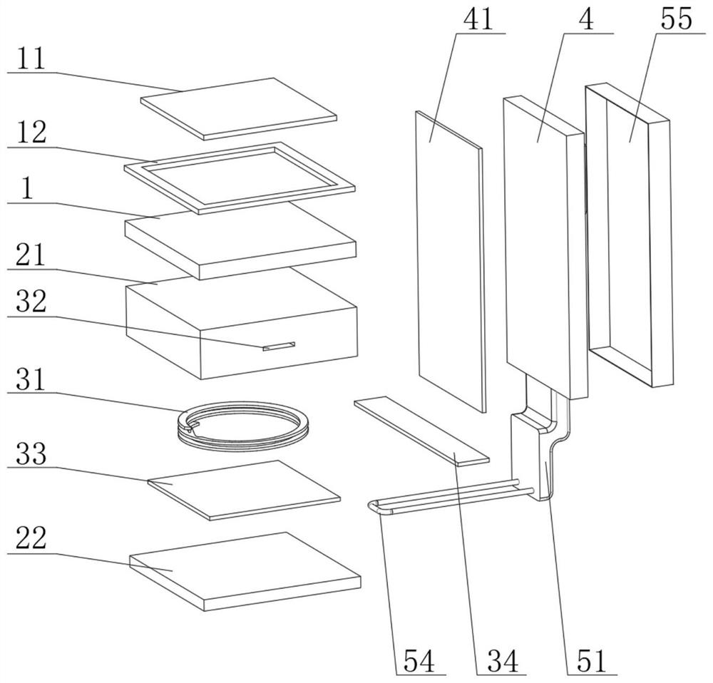
[0029] see Figure 1-3 , an electronic tag for preventing the flow of management and control equipment, comprising a bottom mounting substrate 1 and a side mounting substrate 4, the bottom of the bottom mounting substrate 1 is provided with a bottom vulnerable mechanism 2, and the bottom vulnerable mechanism 2 includes a return-shaped mounting seat 21 and a bottom Fragile strip 22, the bottom fragile strip 22 is fixedly connected to the bottom of the bottom installation substrate 1 through the return-shaped mounting seat 21, the top of the bottom installation substrate 1 is fixedly connected with the top strong viscose 11, and the outside of the top strong viscose 11 is provided with The protection ring 12 is fixedly connected to the top of the bottom mounting substrate 1 .

[0030] In this embodiment, during installation, the operator sticks the bottom installation substrate 1 to the bottom of the equipment support leg through the top strong glue 11, and the protective ring 1...

Embodiment 2

[0032] see Figure 1-3 , this embodiment is further optimized on the basis of Embodiment 1, specifically, the bottom energy storage mechanism 3 is provided inside the return-shaped mounting seat 21, and the bottom energy storage mechanism 3 includes a bottom push plate 33 and a plastic spring 31 , the plastic spring 31 is fixedly connected between the bottom push plate 33 and the inner cavity top of the return-shaped installation seat 21 .

[0033] Specifically, energy storage grooves 32 are opened on both sides of the circular mounting seat 21 , and the energy storage grooves 32 penetrate the circular mounting seat 21 .

[0034] Specifically, the interior of the energy storage tank 32 is slidably connected with an excitation draw bar 34 , and the excitation draw bar 34 is movably connected with the bottom push plate 33 .

[0035] In this embodiment, after the installation is completed, the operator pulls out the excitation drawer 34, and the plastic spring 31 releases the el...

Embodiment 3

[0037] see Figure 1-4 , the present embodiment is optimized as follows on the basis of example 1 or example 2, specifically, a detection mechanism 5 is provided on one side of the side mounting substrate 4, and the detection mechanism 5 includes a connecting belt 51, a solar energy supply plate 52, The detection lamp 53 and two thin wires 54, the side installation substrate 4 is fixedly connected to the bottom installation substrate 1 through the connecting belt 51, the solar energy supply board 52 and the detection lamp 53 are fixedly connected to one side of the side installation substrate 4, and the thin The middle part of the wire 54 runs through the connecting belt 51 and is fixedly connected between the circular mounting base 21 and the bottom fragile bar 22 , and the solar energy supply board 52 is electrically connected with the detection lamp 53 through the thin wire 54 .

[0038] Specifically, the side of the side mounting substrate 4 away from the solar energy supp...


PUM


Abstract

The invention discloses an electronic tag for preventing control equipment from flowing, and relates to the technical field of electronic tags, the electronic tag comprises a bottom mounting substrateand a side mounting substrate, the bottom of the bottom mounting substrate is provided with a bottom vulnerable mechanism, and the bottom vulnerable mechanism comprises a clip-shaped mounting base and a bottom fragile strip; the bottom fragile strip is fixedly connected to the bottom of the bottom mounting substrate through a concentric-square-shaped installation base, a detection mechanism is arranged on one side of the side mounting substrate, the detection mechanism comprises a connecting belt, a solar energy supply plate, a detection lamp and two thin wires, and the side mounting substrate is fixedly connected with the bottom mounting substrate through the connecting belt. According to the invention, through the arrangement of the bottom vulnerable mechanism, the problem that an existing electronic tag lawbreaker for preventing flow of the management and control equipment is easy to counterfeit is solved, and through the arrangement of the detection mechanism, the problem that anexisting electronic tag inspector for preventing flow of the management and control equipment is difficult to visually inspect is solved.

Description

technical field [0001] The invention relates to the technical field of electronic labels, and more particularly relates to an electronic label for preventing the flow of control equipment. Background technique [0002] When the supervisory department manages the outdated or about to be eliminated factory equipment, it is necessary to paste electronic labels on the equipment to prevent the flow of control equipment to prevent existing equipment from flowing between different manufacturers. The existing electronic labels to prevent the flow of control equipment generally pass Electromagnetic signals are monitored and detected, and the cost of counterfeiting by criminals is low. When inspectors inspect, specific instruments need to be used, which is not conducive to the work of inspectors. [0003] In the Chinese patent application number: CN201922266682.1, there is an electronic label to prevent the flow of control equipment, which is composed of equipment labels fixed on the ...

Claims


Application Information

Patent Timeline
Patent Type & Authority Applications(China)
IPC IPC(8): G06K19/077
CPCG06K19/0772
Inventor 郭佳俊
Owner HANGZHOU KUANFU TECH
Learn More